Search filter
7 results found
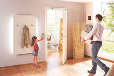
Door dampers - draw-in damper for doors
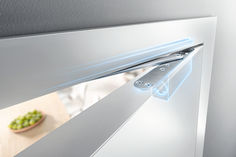
… banging! Door dampers catch closing doors before the thud. They then - softly and silently - close them completely. Whether the movement was triggered manually, or due to the wind or airflow. Smart models ensure soft stopping in the direction of opening and keep doors held open. Door convenience with draw-in damper What can be done to stop doors banging loudly? How do they remain open, even when there is a draught? How can walls and furniture be protected from doors flying open, and fingers protected from doors banging shut? There are a few aids are available for these problems: these cover everything from wedges to floor mounted and wall mounted door stoppers. All of these usually do their job but are often ugly, annoying and impractical. Door dampers perform a better function. They are often integrated into door closers in swing doors, which always automatically close doors after they have been opened. However these are often very loud despite the damping. Damper models such as the types we see in boot lids, cupboards and kitchen drawers are therefore a more elegant solution for internal applications. When pushed, they are slowed by the draw-in damper just before closing and softly moved into end position. Transferring this technology to doors means that they close slowly, quietly and automatically when they are opened only by a gap. In other conditions, they behave like a normal door. Whether consciously perceived or operated intuitively – draw-in dampers always give the feeling of comfort and high quality. GEZE ActiveStop: door dampers for swing doors GEZE ActiveStop is almost invisible when integrated into the door leaf. With the GEZE ActiveStop door damper, slamming room doors, trapped fingers and defects in doors or furniture are a thing of the past. They are able to softly stop and quietly close doors. This works in both directions: no matter whether you give the door a little shove or a powerful push – the door damper reliably and safely catches it in the direction of closing and the direction of opening. Controlled opening and holding open for doors When opening, the system moves the door independently and safely as far as the hold-open position, which can be individually set between 80 to 140 degrees, so the door cannot damage the walls or furniture. GEZE ActiveStop brakes the door at the right time and keeps it open safely in the required position. This means that draughts that help with natural ventilation, for example, are no longer a problem. Doors remain open in the desired position and do not bang shut. Separate door stoppers or door hold-open devices are no longer necessary. GEZE ActiveStop (variant fitted on the frame) © GEZE GmbH Quiet closing after slowed movement Doors run freely at between 25 and 60 degrees. When closing, the door is slowed down when it reaches around 25 degrees thanks to the active dampening. It then closes silently (soft close principle). GEZE ActiveStop therefore not only prevents the door from slamming loudly, but also prevents damage to the door and trapped fingers. The GEZE ActiveStop is also suitable for use in doctor's practices, hotel rooms or hospitals (but not for use with fire protection doors). The draw-in damping on both sides in the integrated variant can be installed in almost any standard, wooden door leaf, and is almost invisible - meeting the highest demands on design. GEZE ActiveStop is available as a variant fitted on the leaf , and a variant fitted on the frame . It can easily be retrofitted on existing wooden or glass interior doors and be removed virtually without trace. This is a big advantage when used in rental properties, for example. GEZE ActiveStop – advantages in the closing direction gentle, controlled slowing and retraction of the door when closing from 25 degrees, adjustable damping performance no uncontrolled slamming of door (from draughts or carelessness) no damage to frame, door leaf, etc. when slamming door minimises the risk of trapped fingers no development of noise door stays shut, no lock (lock case, latch, strike plate) necessary for internal application GEZE ActiveStop – advantages in the opening direction individual back check between 60 and 140 degrees variable opening angle can be set between 80 and 140 degrees protection of the leaf material, walls and other objects comfortable for users (e.g. when carrying a large bag or a child) no floor buffer or wall mounted door stopper necessary Multiple award winning door comfort! Logo German Design Award 2016 The GEZE ActiveStop door damper leaves plenty of room for great style and design, as recognised by numerous awards: German Design Award The integrated version of the GEZE ActiveStop, with an installation width of just 28 mm, is the winner of the German Design Award 2016 in the category 'Building and Elements'. The door damper was also awarded silver in the FocusOpen 2015 by the Design-Center Baden-Württemberg. Logo Focus Open 2017 ICONIC AWARDS and Focus Open At the ICONIC AWARDS 2018 Innovative Interior, the international jury of representatives from the areas of design, commerce and media recognised the GEZE ActiveStop door damper in the building equipment category. The "GEZE ActiveStop fitted on the frame"' door damper received the "Best of Best" award. The GEZE ActiveStop received Silver for the Focus Open 2017 award for the variant fitted on the frame. The Baden-Württemberg Design Centre judging panel recognised the product as an innovative solution with exceptional design quality. More about GEZE ActiveStop GEZE SoftStop for sliding doors Draw-in damper for sliding doors: softly slowing down one or both sides. © Exorbitart / GEZE GmbH GEZE SoftStop has been developed for manual sliding doors, for example in homes or offices. It gently slows the movement of the door before the end of the sliding movement. The door leaves are then guided automatically into the end position. There is therefore no impact on the frame or at the end stop, which protects material - and user's nerves! This means that the risk of entrapment is virtually eliminated. GEZE SoftStops for manual sliding doors can be simply retrofitted on one or two sides. The technology fully disappears into the runner track, becoming an invisible aid. Product features of GEZE SoftStop suitable for the GEZE Rollan, Perlan and Levolan sliding systems invisibly installed in the runner track for light (up to 40 kg) to heavy sliding doors (up to 120 kg) for glass, wooden, metal or plastic door leaves can be used on one or two sides can be integrated with no need for work on the leaves Product videos GEZE ActiveStop Soft stopping process, quiet closing, variable stopping positions. GEZE Perlan 140 with SoftStop Soft retraction of sliding door leaves. Planning Installation Services Planning Installation Services For the most discerning design demands GEZE ActiveStop is almost invisible. The integrated door damper is noticeable only when it is doing its job. Its compact dimensions mean the door damper is virtually invisible, meeting the most discerning design demands. Simple, quick installation GEZE provides support for implementation with service aids. Simple installation is guaranteed with the checklist for the GEZE ActiveStop door suitability test and the GEZE ActiveStop milling template. GEZE ActiveStop can be mounted on wooden interior doors, whether rebated or flush mounted; optimal functionality is assured with up to a 45 kg leaf weight. Variant fitted on the frame: for flexible retrofitting of glass and wooden doors, simple and quick to fit Integrated variant: discrete integration into the door leaf at an installation depth of only 28 mm Durable workmanship for maintenance-free operation GEZE ActiveStop can be individually adjusted: the distance that the door should open and the strength of the damping for opening and closing can be set according to needs and room conditions. is consistently reliable: GEZE ActiveStop is created with sustainable and durable "made in Germany" workmanship. With great functionality and aesthetics and a high level of safety, door dampers offer the highest quality without compromise. Low-maintenance: GEZE ActiveStop is designed for low-maintenance operation. GEZE products Door draw-in damper GEZE ActiveStop surface-mounted configured Door damping on both sides for interior swing doors, configured for timber or glass doors Go to product Door draw-in damper GEZE ActiveStop integrated Door damper on both sides for interior wooden swing doors Go to product Related topics Topics | Security | Fire protection | Self-closing doors Self-closing doors Door closers can save lives in the event of a fire. But they are also useful and convenient in terms of safety, hygiene and energy-saving. Read more Topics | Accessibility Accessibility Accessibility allows everyone to live as equals, self-determinedly, and without external help. It ensures a better quality of life, greater comfort and increased safety for young and old. Read more Topics | Energy efficiency | Ventilation technology | Ventilation Natural ventilation Fresh air from outside - an optimum and healthy indoor climate through a controlled exchange of air through windows activated by electrical motors. Read more
… banging and irritating door damage, but also minimises the risk of injury. GEZE ActiveStop keeps the door open to prevent it from slamming. Separate door stoppers are no longer needed. The holding position can be set individually using the adjustable opening angle. Damaged walls or furniture behind doors are not only unsightly, but most of all unnecessary. GEZE ActiveStop brakes the swing upon opening and stops the door in the desired position. Door control GEZE ActiveStop
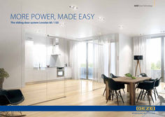
… banging into the frame or buffer, reduced chance of finger entrapment Sleek design • • Track only 50 mm high Fittings integrated into the track under a sleek covering profile Flexible use • • • Mounting to the wall, the ceiling or a glass fan light Optional hidden ceiling mount Extremely small outer measurements (50 x 50 mm) Diverse leaf materials • • Utilise all conventional leaf materials Glass (8 to 12,76 mm), wood, metal or synthetic material Multiple uses for individual system components Small number of individual components Special roller carriers • • • Excellent load distribution Silent running performance Tested in accordance with EN 1527, EN 1670 and ANSI/BHMA A
Self-closing doors
… banging loudly. Various models feature different setting options. In addition to the closing force, the closing speeds, latching action and back check can also be set. This is usually works using adjustable valves. When adjusting the door closer, ensure that the right tool is always used to prevent damage. Download the recommended settings for GEZE door closers (PDF | 764 KB) GEZE TS 5000 ECline: overhead door closers with opening assistance Fire protection versus access for all Doors with manual door closers are often difficult to open because opening the door requires a certain amount of energy, which is then used for the closing process. These doors present an obstacle to older people and children, and do not therefore meet access for all demands. DIN 18040 is a key standard which defines barrier-free construction in Germany. This standard sets a maximum applicable operational force of 47 newton metres for self-closing doors. If a standard door closer cannot create an opening movement which is sufficiently effortless, then specific equipment options, for example via integrated opening assistance or via a free swing function, can be used to do this. GEZE free swing door closer brochure (PDF |
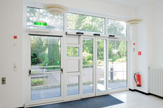
Emergency exit protection - safety technology for emergency exits
… bang in a shopping centre, takes virtually everyone by surprise, resulting in uncontrolled mass panic. It is precisely such sudden events that present a particular risk to our safety. A safe place very quickly becomes a life-threatening area that needs to be evacuated as quickly as possible. Flight as a human reaction to acute danger People react to danger in many different ways. Very few remain quiet and composed; most descend into panic and act irrationally. But generally speaking, we all have one thing in common: the urge to get away from the dangerous situation. The natural reaction to this is to flee. Faced with an acute danger in a building, the people caught up in it are confronted with structural and spatial realities: walls, stairs and fixings suddenly become obstacles which make quickly leaving the building more difficult. People in a state of fear or panic may also lose their sense of direction and so increase the risk to their lives. Escape routes save lives © GEZE GmbH Escape and rescue routes can save lives in dangerous situations. In a hazardous situation, clearly identified traffic routes lead people out of the building or into a secured area as quickly as possible via emergency exits or panic doors. At the same time, they allow the fire service or an emergency doctor to take quick rescue action from outside. Special legal and building regulations apply to guarantee safety by means of escape and rescue routes. In Germany, these are defined in the Technical Rules for Workplaces. These regulations ensure that emergency exit protection (or escape route protection) always takes top priority. Additionally, state-specific building regulations need to be taken into account when designing escape routes and emergency exits in Germany. According to the Technical Rules for Workplaces, an escape and rescue route guarantees safety only when specific guidelines are taken into account. Guidelines for escape and rescue routes Layout and dimensions of escape routes Structural and technical design of escape routes Identification of escape routes Safety lighting for escape routes Creation of escape and rescue route plans Emergency exits: where various functional demands interact Doors must meet various demands depending on their intended use. These can be optimally combined by using different system components, however. Early planning in terms of the intended use is an important part of this. For escape and rescue routes, the most important challenge is to allow people to evacuate the building quickly and safely. When there is no danger present, however, the doors must remain closed and protect against unauthorised access. In particular, it is important for the building operator to protect the facilities against sabotage, burglary, theft or misuse. Emergency exit functionality in emergency situations Emergency exits are a significant part of escape and rescue routes. The layout and number of emergency exits depends on the building and the respective building regulations. One this is certain: emergency exits must allow people to quickly evacuate the hazardous area at any time. Being able to open doors speedily and simply without any external aids is critical. Emergency exits must open immediately in the direction of escape and must lead those in danger to the outside, or into protected areas. According to new European standards, emergency exits can be equipped with a variety of emergency exit locks. The optimal selection of emergency exit locks depends on how many people need to evacuate in an emergency. If there is a risk of mass panic, panic exit devices should be integrated into the doors in accordance with DIN EN 1125. These consist of a horizontal bar combined with a panic lock, which may be a mechanical, electro-mechanical or motor panic lock. In public buildings in particular, visitors are not familiar with the on-site escape routes and functions of the emergency exits. If they press against the door leaf in the direction of emergency exit, panic exit devices allow the door to open in less than a second with no instructions. If the number of people in the building is manageable, and they are familiar with the escape routes, emergency exit devices according to DIN EN 179 are usually sufficient. For example, the horizontal bar can be replaced by a door handle since there is no chance of panic. Functionality of emergency exits in normal operation Emergency exits are very often used in fire protection sections. The safe flight function is just as important as the self-locking and fire-proof features of the door installation. If automated doors need to provide complex functions in escape and rescue routes, a system solution comprising a door control unit, an electronic locking element such as escape door locks or emergency exit electric strikes for example, and a panic lock (also called anti-panic locks) is recommended. This guarantees both protection against unauthorised access on the one hand, and free access for people evacuating in the event of a hazard on the other. Doors are one of the most important components in the safety design of a building. Thomas Borgmann, safety technology segment manager, GEZE GmbH Escape routes must be clearly identified in buildings. © Morten Bak / GEZE GmbH The door control unit, as the 'brain' of emergency exit control, assures and monitors the opening and closing procedures in escape routes. The self-locking panic lock guarantees quick opening in an emergency, while the door control unit controls access. Activated by a fire alarm system, or in the event of a power failure, it automatically locks if a motor lock is used. The door can still be passed through in the direction of emergency exit since the emergency exit closure is automatically unlocked in the event of a fire alarm or power failure. The door also opens via the emergency button on the door control unit if several people push against it in a panic situation. The door can be opened from the outside using a key at any time. If a self-locking panic lock is used, this guarantees protection against burglary in the opposite direction to the direction of emergency exit in accordance with insurance requirements. With this trio, automatic swing doors in normal operation are closed by self-locking of the panic lock, and can be controlled and secured by the door control unit. At set times, such as daytime operation, the door control unit can release the door. Otherwise, it permits controlled individual release via a key or an access control system. In the event of danger, the door can be operated at any time by pressing the emergency push button of the door control unit. Guaranteed safety is crucial in an emergency: GEZE door control units are tested in compliance with eltVTR (guidelines for electronic locking systems) and TÜV (technical supervisory association), and panic locks in compliance with the standards DIN EN 179, 1125, 12209, 13637, 1627 and 1634-1 applicable for locks. Emergency exits influenced by pressure ventilation systems pressure ventilation systems help to keep rescue routes smoke-free in the event of a fire, for instance in staircases. In addition, pressure ventilation systems are used in buildings where a large number of people are present who may not be able to rescue themselves in case of a fire. These include homes for the elderly, hospitals, nursery schools, etc. Fire protection doors near pressure ventilation systems need particularly detailed planning; they may otherwise not be able to offer barrier-free access or may not close reliably in certain circumstances. Fire protection doors in smoke protection pressure stairwells For doors with a direction of emergency exit leading into a staircase, the high pressure is on the hinge side. This means that they are more difficult to enter if the smoke protection pressure feature is activated since the user has to overcome both the resistance of the door closer and the counter-pressure. In this situation, the focus is on the opening process if the smoke protection pressure system activates. If barrier-free access needs to be ensured both when the system is active and when it is not, then a drive unit such as the Powerturn F must be used on such doors. Fire protection doors from the PVS staircase For fire protection doors leading out of a staircase, the higher pressure is on the opposite hinge side. This does make them easier to open if the smoke protection pressure system is active, but the door must also close securely against the pressure. Because of this, the differential10 pressure must be taken into consideration and the closing force of the door closer must be adjusted accordingly. GEZE also offers assistance for this application with the TS 5000 SoftClose. With this device, the last 15 degrees of the opening angle are controlled using a separate valve, so that the door leaf can be accelerated using a latching action, or decelerated over the last few degrees of opening in a targeted fashion. This helps manage the pressure situation, and ensure the door closes safely. An important consideration for wider doors and higher pressures is that the door closer must generate the stipulated closing force to close securely against the pressure. In everyday use, such doors are very difficult to operate and are not barrier-free. Safe rescue routes with intelligent GEZE technology The demands on safety and security components are almost as varied and individual as each specific building. Certain additional specific demands also need to be met. GEZE safety solutions are able to guarantee safe escape and rescue routes in any building. If the escape and rescue routes should not be open to everyone in normal operation, GEZE access control systems – which are connected to door control units – can take over the necessary monitoring. Whether at airports, in hospitals or at conference centres: the multifunctional products supplied by GEZE are like cog wheels which engage neatly into one another, producing an emergency exit system that not only provides optimal protection in an emergency and convenience during normal operation, but one that can be planned and installed reliably. Good to know: The GEZE emergency exit system solution is approved and certified by an independent institution in accordance with the EltVTR (guidelines for electronic locking systems). Go to the GEZE emergency exit systems Emergency exit protection in the Vector headquarters in Stuttgart The new company headquarters of Stuttgart-based IT specialists Vector Informatik is the largest building in the company complex so far. The company opted for safe escape and rescue routes with intelligent technology by GEZE. Learn more here! Go to the Vector company headquarters in Stuttgart GEZE reference project Planning Installation Services Planning Installation Services Individual solutions Personal safety is the top priority when planning a building. Escape and rescue routes must therefore be considered from the outset. In addition to constructional demands, there are also legal regulations to comply with. Every building should have a tailor-made security concept with optimal emergency exit protection: fire and danger alarm systems, access control systems in combination with a door control unit and a door closer system, escape door locks or motor locks are just some of the possible variants. Planning the general design and layout of doors in a building at an early stage is important to prepare for subsequent adjustments and retro-fitting. GEZE offers solutions for securing emergency exits that are tailored towards specific demands and individual escape route concepts. GEZE also has many years of international experience in providing consultancy in fire protection planning for all types of buildings and can support you as a project manager. The most stringent safety standards combined with simple installation The key challenge in emergency exit protection is how to optimally combine the contradictory demands of normal operation and emergencies. To create an escape route that doesn’t simultaneously serve a getaway for thieves, for example, it must be locked to unauthorised persons. This is particularly relevant for department stores. As a safety technology specialist, GEZE offers a wide range of products and optimal system solutions to guarantee unrestricted safety of the escape route in the event of a hazard. Customised solutions combine individual safety demands in one intelligent system so that emergency exits are opened and closed in a coordinated way in an emergency. All GEZE components can be simply and quickly integrated into an emergency exit system at any time. They meet the highest safety standards using state-of-the-art technology. The wide range of GEZE products and systems is also operator and user-friendly, durable and economical. A cross-product approach and the interaction between door, window and safety technology products mean that end users and fitters can rely on sophisticated and coordinated solutions. Expert maintenance guarantees durability and perfect functioning The operators of the buildings or rooms are responsible for keeping the escape routes well maintained, and for taking all necessary precautions to guarantee personal safety and protection of the building. To maintain the functional safety of doors in escape routes in compliance with standards, these doors need regular maintenance. The components in emergency exits must be maintained annually, either by the manufacturer or by one of his approved partners. As part of this, all of the safety and control devices of the door installation must be checked in accordance with the legal regulations. A monthly inspection by the operator is also recommended. GEZE offers a full service from the planning of a building, installation and commissioning through to service during ongoing operation. Downloads You can find GEZE brochures on the topic of emergency exit protection available for download as a PDF here. Emergency exit safeguarding brochures TZ 320 door control unit flyer (pdf | 48 KB) FTV 320 escape door lock flyer (pdf | 425 KB) Building security brochure (pdf | 434 KB) Emergency exit system brochure (pdf |
Accessibility for buildings: Tips on planning, DIN standards and laws | GEZE
… banging doors. Door dampers catch closing doors before the “thud” And then silently close them completely. Read more Topics | Security | Emergency exit protection Safeguarding emergency exits Doors that are always open and yet safely locked - escape and rescue routes have to meet some tough challenges. Intelligent emergency exit system solutions by GEZE are the perfect solution for this apparent contradiction. Read more
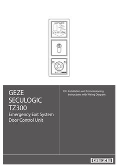
GEZE SECULOGIC TZ300 EN Installation and Commissioning Instructions with Wiring Diagram Emergency Exit System Door Control Unit … SECULOGIC TZ300 Contents … 1. About this document … … . … . … . … . Product description … Related documents … Key to symbols … Abbreviations … 2. Safety and responsibility … … . … . … . General safety instructions . … Target readership and qualifications … Product liability … 3. Installation and assembly … … . … . … . … . … . Preconditions … Installing the flush-mounted door control unit … Fitting the surface-mounted door control unit … Replacing the lock cylinder … 11 Fitting a safety cylinder, length 40/10 … 11 4. Commissioning … 12 … . … . … . … . Preconditions . … 12 Settings … 12 Description of basic functions … 12 Fire detection system (BMA), hazard alert system (GMA), smoke and heat extraction system (RWA) … 13 5. Operation … 14 … . … . … . … . … . … . Controlling door control unit TZ300 with the key switch … 15 Opening doors in emergencies and triggering alarm … 16 Cancelling alarms … 17 Alarm signal … 18 Removing alarms and system faults … 19 Mains failure … 19 6. Wiring diagram … 20 … . … . … . … . … . … . … . … . … . General information … 20 Markings … 20 Current consumption … 20 Door control units … 21 Locking elements … 26 Key switch … 29 Access control … 32 Timer … 33 IQ Lock EM, lever locks … 34 7. … . … . … . Appendix … 36 Commissioning check list … 36 Glossary of terms … 37 Data sheets … 38 SECULOGIC TZ300 … About this document About this document These instructions describe the installation and commissioning of the GEZE TZ300 door control unit. … Product description The GEZE door control unit is part of the SecuLogic emergency exit system. It is designed for controlling and monitoring electrically interlocked emergency exit doors. It secures doors along emergency exit routes against unauthorized access. At the same time the built-in emergency stop pushbutton allows instant passage in the event of an emergency. Through a built-in interface a smoke and heat extraction, burglar alarm or hazard alert system can be connected, which unlocks the door in an emergency to allow an escape from the building. External signal transmitters, such as alarm bells or warning lights can be connected as well as an alarm signalling interface to the building services management system. Built-in buzzers and LEDs provide visual and audible indication when an alarm has been triggered. … Related documents All components are supplied with data sheets containing their technical specifications. These data sheets, as well as further documentation, is available on the Internet under www.geze.de/SecuLogic. … Key to symbols Warning In these instructions, warnings are used to warn against material damage and injuries. XX Always read and observe these warnings. XX Follow all instructions marked with the warning symbol and the word WARNING. Warning symbol Warning WARNING Meaning Danger for people. Serious or fatal injury can occur if these instructions are not observed. Further symbols used in these instructions Important information and technical notes are emphasised to illustrate the correct operation. Symbol Meaning means “Important note” means “Additional information” XX Symbol for a user action. Observe the sequence if there are several action steps. … About this document … Abbreviations Abbreviation AKRR BLE220 BMA FS FTÖ GCDU100 GCDU200 GCFP401 GCRR200 GCVR200 GLT GMA IQ Lock C IQ Lock EL IQ Lock EM IQ Lock M KZF MA500 NC NO NOT320 PSU OKFF RR RWA SCT221 SCT222 SCT320 SHB220 SLE220 SLH220 TZ300S TZ300S ZSU … SECULOGIC TZ300 Meaning Feedback contact interlocked (actuated by the anchor) Flashlight Fire detection system Latch lock Emergency exit door opener Single-door unit Door unit Fingerprint RFiD card reader RFiD card reader Building services management Hazard alert system Self-locking contact lock Self-locking motor lock Self-locking lever lock Self-locking mechanical panic lock Short-term release Holding magnet Floating NC (normally closed) contact Floating NO (normally open) contact Emergency button Power supply unit Upper edge of finished floor “Door closed” feedback contact (actuated through sliders on the latch) Smoke and heat extraction system Key-operated pushbutton, single-pole pushbutton (NO), extendable to single-pole reversing (two NO) Key switch with LED indicator, single-pole reversing (two NO) Key switch, single-pole reversing (two NO) Alarm bell with flashlight Signal lamp Alarm bell Door control unit with key switch (connection through ribbon cable) Door control unit with key switch and built-in PSU Timer SECULOGIC TZ300 … Safety and responsibility Safety and responsibility The GEZE door control unit has been designed according to the latest technical standards and acknowledged safety rules and regulations. Dangers can, nevertheless, occur in its installation and use. You must therefore observe the following instructions. … General safety instructions XX XX XX XX XX XX XX XX Installation, commissioning and repairs must be performed only by GEZE-authorized specialists. Use only genuine GEZE parts for repairs. GEZE accepts no liability for damage arising from unauthorized modifications to the installation. Primary building safety measures must be taken by the owner. Cables must be laid according to standards VDE 0100 and VDE 0815. To prevent unauthorized access, never leave the key in the key switch. Doors with electrical locks along escape routes should be inspected annually by a specialist. The specialist must issue a certificate verifying the periodic inspection, which the owner must submit to the building inspectorate on request. The inspection can be performed by a GEZE service technician or a GEZE-authorized service provider as part of a maintenance contract. In addition, GEZE recommends a monthly inspection of the emergency exit system for visible damage and faults by the owner. Any identified damage or faults must be rectified immediately by a GEZE service technician or a GEZE-authorized service provider. Intended use The GEZE door control unit is intended for controlling and monitoring electrically locked emergency exits. Thirdparty products must be used only after consultation with GEZE. Improper use Improper use includes the connection of any products that are not expressly approved by GEZE. … Target readership and qualifications Installation, assembly, commissioning and repairs must be performed only by GEZE-authorized specialists. … Product liability àà According to manufacturers’ liability for their products as defined in the German product liability act, the information contained herein and in the associated installation instructions and wiring diagrams (product information and intended use, incorrect use, product performance, product maintenance, obligation to inform and obligation to provide instruction) must be observed. Non-observation frees the manufacturer from their liability. àà Installation, function testing and maintenance must be performed only by GEZE-authorized personnel. GEZE accepts no liability for damage arising from unauthorized modifications to the installation. àà A combination with third-party devices invalidates GEZE’s warranty. For repair and maintenance, use only original GEZE parts. … Installation and assembly … SECULOGIC TZ300 Installation and assembly Warning! Risk of death through electric shock. XX Installation and assembly must be performed only by GEZE-approved specialist personnel. XX Check that all cables are voltage-free before installation. … Preconditions àà àà àà àà àà … Cables are routed according to GEZE cabling diagram Miniature circuit-breakers as primary, mains-side disconnectors Observation of standards VDE 0100 und VDE 0815 for laying cables Tamper-proof cable routing according to VDE 0833 (surface-mounted cables in steel conduit) For flush-mounted cabling, flush-mounted sockets (depth … mm) at a mounting height of 850 mm from floor surface and up to 1200 mm for the emergency button Installing the flush-mounted door control unit These instructions describe the recommended installation of the a flush-mounted door control unit using the TZ300SN as an example. … 2 … 7 … 6 … 1 … 3 … 5 … 7 … Emergency exit label Frame PSU NET220 Terminal blocks Ribbon cable Control unit with emergency pushbutton TST300 Key switch SCT320 SECULOGIC TZ300 XX XX Installation and assembly Lay mains cable and ribbon cable in the flush-mounted sockets. Connect cable to terminal blocks according to wiring diagram. ,5 62 60 850 - 1200 71 XX XX 71 Connect and fit the PSU. Connect the key switch door control module with the ribbon cable. … Installation and assembly XX SECULOGIC TZ300 Fit the terminal blocks to the back of the door control unit. C D C D XX Fit the door control unit. Fit the green adhesive frame. XX Test the unit’s function. XX … SECULOGIC TZ300 … Installation and assembly Fitting the surface-mounted door control unit … 1 Door control unit TZ300SN … Terminal blocks … XX Open the housing. … Installation and assembly Fit the wall-mounting bracket near the door (height of emergency button: 850 mm – 1200 mm from floor surface). 850 - 1200 XX SECULOGIC TZ300 Take off the mains connection cover. Connect the 230 V cable to the screw terminals of the PSU and refit the cover. XX Connect cable to terminal blocks according to wiring diagram. XX Fit the terminal blocks to the back of the door control unit. XX Secure loose cables with cable ties. XX XX Hook in housing and secure with screws. Fit the cover of the emergency button. XX Test the unit’s function. XX Apply the labels “EMERGENCY” and “Press only in emergency” in the required language on the provided fields on the emergency exit sign. The required adhesive labels are supplied separately in English, French, German and Norwegian. XX XX 10 SECULOGIC TZ300 … Replacing the lock cylinder The lock cylinder must fulfil the following requirements: àà Profile half-cylinder, 40 mm (30/10) àà Eight-way adjustable When the plant is in operation, disable tamper switch. àà To do this, turn key to left for ten seconds. Right LED lights up green. The left LED goes out. Tamper alarm function is disabled for two minutes. XX Take housing off the wall bracket. XX Unscrew key switch. XX Release cap screw and remove the lock cylinder. XX … Fitting a safety cylinder, length 40/10 If using a safety cylinder with 50 mm (40/10), use the spacers between key switch and housing. Fit the spacers before the carrier plate; this moves the complete fixture to the back by 10 mm. The spacer set is not included as standard with the door control unit. The set also contains four longer screws, which must be used instead of the existing screws. XX XX XX XX Replace the lock cylinder. Fit a new lock cylinder and secure with cap screw. Reassemble the door control unit in reverse order to disassembly. Test the unit’s function. 11 Commissioning … Commissioning … Preconditions SECULOGIC TZ300 Doors with electrical locks along escape routes must be taken into operation after the manufacturer has certified their suitability for the intended purpose. In addition, the correct installation and correct function of the electrical lock must be verified by a specialist. … .1 Tamper switch TST300 When operating voltage is applied to the TZ300, a tamper alarm is triggered if the emergency button’s hood is not fitted. … .2 Tamper switch SCT320 (on UP only) When operating voltage is applied to the TZ300, a tamper alarm is triggered if the emergency button’s hood is not fitted. If the tamper switch of the key switch is not to be evaluated, you must fit a jumper between terminals … and 54. … .3 Disabling the tamper alarm For maintenance, the tamper alarm can be disabled for a limited time. To do this, turn the built-in key switch to the left for about ten seconds. This disables the tamper alarm for about two minutes. While it is disabled, the right LED is lit green and the left LED is off. To reenable the tamper alarm before the two minutes are up, turn the built-in key switch to the right. The door control unit is then unlocked. To lock it, turn the key switch to the right again. … Settings No settings can be made or changed on the door control unit. All values, such as short-term release, cancelling, pre-alarm, etc. are permanently set. … Description of basic functions … .1 Short-term release (KZF) Short-term release releases the emergency door protection for a limited time. During this time, access through the door is possible without triggering an alarm. It is activated with the built-in key switch or an external actuator connected to the short-term release input. The short-term release duration is about 20 seconds. … .2 Cancellation of short-term release When short-term release is active, the door locks prematurely when it is closed before the short-term release time has expired. This prevents unauthorized access through the door after an authorized person has gone through. … .3 Retriggering on short-term release If the short-term release function is triggered again while the function is still active, the short-term release period starts again. … .4 Pre-alarm If the door is passed through after the short-term release time has expired, an audible signal is issued to warn the user that the short-term release time has expired. The pre-alarm duration is 60 seconds. If the door is closed while a pre-alarm is active, the door is locked again automatically and the pre-alarm is reset. 12 SECULOGIC TZ300 … .5 Commissioning Door alarm If the pre-alarm time is exceeded, the door alarm is triggered. This must then be reset with the built-in key switch or with a new short-term release command. If the door is closed while the door alarm is active, it locks and can be unlocked again only after the alarm has been reset (except when the emergency button is pressed or emergency unlocking is triggered). The door alarm is also triggered when the door is opened forcefully. … .6 Unlocked The power supply to the locking element is permanently interrupted. The door can be passed through without triggering an alarm. … .7 Locked The locking element is energized through the door control unit. The emergency door protection is active and unauthorized people can open the door only by pressing the emergency button, which triggers an alarm. … .8 Emergency unlocking The TZ300 can be unlocked in an emergency by the fire detection, burglar alarm or hazard alert system. This is a non-safety-relevant interruption of the power supply to the locking element. When the BMA, GMA or RWA signal is cancelled, the alarm is automatically reset after 60 seconds. … .9 Direct unlocking (according to EltVTR) Safety-relevant interruption of the power supply to the electrical lock through an NC contact when the emergency button is pressed. … Fire detection system (BMA), hazard alert system (GMA), smoke and heat extraction system (RWA) … .1 Alarm triggers If the BMA, GMA or RWA signal of a door control unit is applied, it is unlocked and a local alarm is triggered (audible through built-in buzzer and visual through built-in LED). The system remains unlocked as long as the signal is applied and until the alarm has been reset. See … .3, “Resetting the alarm”. The alarm is triggered through a floating NC contact. If no BMA, GMA or RWA exists, a 2K resistor must be fitted across the Fire Detection System input (terminals … and 10, orange terminal field. This is the as-supplied state. If a BMA or GMA system is connected, the 2K resistor at the emergency unlocking input of the TZ300 (terminals … and 10) must be removed and connected in series with the NC contact of the BMA or GMA. … .2 Cable monitoring according to prEN 13637 For installations according to prEN 13637 the cable between fire detection system and door control unit must be monitored. A 2k resistor must be fitted in series with the NC contact at the fire detection system output for this purpose. … .3 Resetting/acknowledging the alarm When the BMA signal is cancelled, the alarm is automatically reset after 60 seconds. The visual and audible signal at the TZ300 goes out and the door control unit locks the door. The system can be reset before the 60 seconds have expired with the built-in key switch of the TZ300. To unlock the system after a reset, turn the key to the left for more than one second. To lock the system after a reset, turn the key to the right. 13 Operation … SECULOGIC TZ300 Operation … 2 … Emergency exit label … Key switch … Control unit with emergency button … “Locked” LED … “Door state” LED … “Alarm” LED … No. … 2 … 14 Indicator Colour Meaning Red Locked Green Unlocked Green flashing (every second) Short-term release Red Door closed Green Door open Yellow Alarm Yellow flashing (every second) Pre-alarm Yellow flashing Fault SECULOGIC TZ300 … Operation Controlling door control unit TZ300 with the key switch Unlocking the door When the system is unlocked, the locking elements are disabled and the door can be opened. XX Turn the key to the left and hold it for about one second. … 1 … LED … lights up green. The door is unlocked. Locking the door When the system is unlocked, the locking elements are enabled and the door can not be be opened. Preconditions: The door is closed; otherwise a pre-alarm is triggered. XX … Turn the key to the right. … 3 LEDs … and … light up red. The door is locked. 15 Operation SECULOGIC TZ300 Unlocking the door temporarily (short-term release = 20 seconds) With the short-term release function, the door can be unlocked with the key switch for 20 seconds. When this time has expired, the door is locked again. àà If the door is not closed after short-term release time has expired, a pre-alarm is issued. àà If the door is closed after the short-term release time has expired, the door is locked again. àà If the short-term release function is triggered again while the function is still active, the short-term release period starts again (is retriggered). Precondition: The door is locked. XX Turn the key to the right. … 2 … LED … flashes green. The door remains unlocked for the set period of 20 seconds. On cancellation the LED lights up red. … Opening doors in emergencies and triggering alarm When the emergency button is pressed the door’s locking elements are de-energized and the door can be opened (direct unlocking). If a connected fire detection or similar system triggers, the locking elements are de-energized automatically to release the door (emergency unlocking). XX … Press the emergency button. … 3 LED … lights up green and LED … lights up yellow. The door is unlocked. The alarm is triggered. 16 SECULOGIC TZ300 … Operation Cancelling alarms Alarms of the door control unit remain active until their cause has been eliminated and the alarm is acknowledged at the door control unit. (Exception: emergency unlocking through BMA,GMA or RWA, after which the alarm is automatically reset after 60 seconds; see section … .3.) … .1 Resetting emergency button When the emergency has passed, the emergency button must be reset. XX Remove emergency button cover. XX Turn emergency button to the right. The emergency button returns to its normal state. XX Refit the cover. XX Acknowledge the alarm. … .2 Acknowledge alarm Precondition: The alarm cause has been eliminated. To acknowledge the alarm and lock the door XX Turn the key to the right To acknowledge the alarm and unlock the door XX Turn the key to the left The door alarm can also be acknowledged through the short-term release input. A tamper alarm can be acknowledged only 30 seconds after the alarm cause has been eliminated. For the duration of the tamper alarm the TZ300 remains locked. It can, however, be unlocked with the emergency button. If the alarm can not be acknowledged with the key switch, a new alarm may be active. If, for example, the cover was not refitted after resetting the emergency button, a tamper alarm is triggered when emergency unlocking is acknowledged, and the door control unit locks the door. This is indicated by a change in the sound of the audible signal. 17 Operation … SECULOGIC TZ300 Alarm signal Misuse of the system and emergency situations are indicated by a built-in buzzer and yellow alarm LED 3. An alarm can, in principle, be acknowledged only when its cause has been removed. Alarm Pre-alarm Alarm LED Alarm bell Yellow flashing light Acoustic signal, … beeps (1 s on, … s off) Door alarm Yellow continuous light Acoustic signal, … seconds continuous Tamper alarm Yellow continuous light Acoustic signal, … beeps Alarm Yellow continuous light Acoustic signal, … seconds continuous - Unlocking through emergency button - Triggering trough BMA/GMA System fault 18 Yellow flashing light No acoustic signal at … second interval SECULOGIC TZ300 … Operation Removing alarms and system faults Alarm state Cause of alarm Pre-alarm Door not closed after unlocking period has expired. No closed signal No closed signal Door alarm Elimination of alarm cause XX XX XX XX Tamper alarm No locked signal Tamper switch of door control unit not closed (on UP only). XX XX XX XX Alarm Key switch tamper switch not closed. Emergency button of TZ300 pressed (direct unlocking). Fuse in TST300 blown. XX XX XX Emergency unlocking through connected BMA, GMA or RWA. XX XX 2K resistor between terminals … and 10 not set and no BMA, GMA or RWA connected. Locking element connected with reversed polarity. Emergency button LED goes on and off. Other LEDs remain off. (With PSUs NET220 und NT19.2-24. With larger PSUs the fuse blows.) Locking element not connected. Jumper on FTÖ331U was not removed. FTÖ332 is connected without RP220. Short-circuit in the supply line of the lockingelement. XX XX XX XX XX XX XX XX Controller defective XX Close door. Unlock door. Close door. Check door contact. Check locking element. Close contact. Fit cover. After suppression time,acknowledge alarm. Reset door control unit emergency button. Check fuse. Replace fuse. Check BMA, GMA or RWA and switch off emergency unlocking signal. Check input of affected door control unit. Fit a 2K resistor between terminals … and 10. Immediately isolate from the power supply and connect correctly. Connect locking element. Remove jumper on FTÖ331. Check locking element supply line for short-circuit. Connect FTÖ332 with RP220. Press emergency button. Release (pull out) emergency button. Replace door control unit. When the alarm cause has been remedied, the alarm must be acknowledged with the built-in key switch. … Mains failure When mains power is restored, the door control unit is always in operating state Locked. If an alarm is active when mains power is restored, the door control unit is in operating state Alarm. Operating mode before mains failure Operating mode after mains failure Locked Permanent unlocking Short-term release Alarm Locked Locked Locked Alarm or acknowledge alarm if cause no longer exists 19 Wiring diagram SECULOGIC TZ300 … Wiring diagram … General information Unless otherwise stated, the wiring diagrams apply to surface-mounting versions and flush-mounting versions from TS300, software version … . … Markings The wiring in these wiring diagrams are marked as follows: … Colour Former designation to DIN 47002 New designation to DIN IEC 757 Colour Former designation to DIN 47002 New designation to DIN IEC 757 Black Brown Red Orange Yellow Green sw br rt or ge gn BK BN RD OG YE GN Blue Violet Grey White Pink Turquoise bl vi gr ws rs tk BU VT GY WH PK TQ Current consumption When connecting external devices, observe the overall power consumption. àà Output rating for external devices through standard PSU: àà Flush-mounted version (NET220): 24 V DC, max. 350 mA àà Surface-mounted version (NT19.2-24): 24 V DC, max. 650 mA àà Output rating for external devices through external PSU (Net24-5, Logo): … A … .1 Consumer Consumption in mA (approx.) Consumer Consumption in mA (approx.) Door control unit TZ300 Control module TST300 120 100 Holding magnet MA500 Emergency exit door opener FTÖ331 Emergency exit door opener FTÖ332 Relay card RP220 250 160 105 10 Numerical code lock CTI / CTS V Signal lamp SLE220 Flashlight BLE220 Alarm bell with flashlight Alarm bell SLE220 Key switch with LED SCT222 50 85 90 110 16 30 Single-door unit GCDU100 Door unit GCDU200 Master unit GCMU200 GCMDU200 Master unit GCMU524 30 120 120 120 130 Fingerprint reader GCFP401 Card reader GCRR200 Card reader GCVR200 Smoke switch RS5 200 100 100 19 IQ Lock EM / EM DL, 24 V version IQ Lock EL / EL DL with controller MST210 210 250 Examples for calculating the total power consumption Example 1: Single-leaf emergency door with 1×TZ300SN UP (120 mA), 1× FTÖ331 (160 mA) and 1× SLE220 (85 mA). Total current consumption of all devices = 365 mA; external devices = 245 mA (without TZ300) Conclusion: PSU NET220 with 500 mA of the TZ300SN UP is sufficient. Example 2: Two-leaf emergency door with TZ300SN AP (120 mA), 2× MA500 (250 mA), SCT222 (30 mA) and RP220 (10 mA) IQ Lock EM DL 24V (210 mA) Total current consumption of all devices = 870 mA; external devices = 750 mA (without TZ300) Conclusion: PSU NT19.2-24 with 800 mA of the TZ320SN AP is not sufficient. Solution 1: For IQ Lock EM DL, use separate PSU (NT6.3-24, 260 mA, No. 109637) Solution 2: Use TZ300S without PSU and draw power from external PSU. (e.g. NT24-5, 24 V, … A No. 111182 or Siemens Logo 24 V, … A, No. 078401) 20 SECULOGIC TZ300 … Wiring diagram Door control units Programming interface orange Door LED blue Latch LED Emergency button LED red Tamper switch Buzzer Alarm LEDs … .1 Door control unit TZ300 (terminals, fuses) Fuse Name Value Meaning F1 … A, SMF 125 V, quick-acting 24 V external Operator control and display elements àà Latch LED àà Door LED àà Alarm LED àà Buzzer (75 dB at about 50 cm distance) Technical specifications Current consumption: 100mA Supply voltage for external devices: àà with standard PSU of the TZ300: àà with external PSU: UP: NET220, max. 350 mA; AP: NT19.2-24, max. 650 mA max. 800 mA (use only GEZE-approved PSUs) Terminal assignment Max. cable cross-section for screw and plug-in terminals: … mm² X103 X100 X101 X102 Terminal blade terminal for GEZE key switch red terminal field … 3 orange terminal field … 6 14 15 … 2 … 10 … Blue terminal field … 22 21 20 … Function Supply GND 24 V DC supply Locking element, +, 24 V DC Locking element, -, GND Door locked feedback Door closed feedback 24 V DC 24 V DC Brief unlocking input Emergency unlocking input 24 V DC 24 V DC NO, alarm output Com, alarm output Max. … A, 24 V DC NC, alarm output GND 21 Wiring diagram … .2 SECULOGIC TZ300 Notes about the wiring diagram The notes apply for the following wiring diagram of the various versions of the TZ300. 1) Building mains fuse. 2) The primary and secondary sides must be spatially separated. For the TZ300S the PSU must be fitted externally. 3) TZ300SN UP: Protection class II, PE (protective earth) conductor is not connected. TZ300SN AP: Protection class I with PE conductor testing according to VDE0100. 4) In delivery state the 2K resistor is fitted. When connecting a BMA, GMA or RWA, remove the resistor and connect it in series with the NC contact of the BMA, GMA or RWA (see plan “Emergency unlocking through BMA, GMA or RWA”). 5) Contact closed when door closed. 6) When a GEZE alarm bell or siren is fitted, a jumper must be set. 22 SECULOGIC TZ300 … .3 Wiring diagram Door control unit TZ300S, TZ300SN blue For notes about the wiring diagram, see section … .2 23 Wiring diagram … .4 SECULOGIC TZ300 TZ300SN, TZ300S: Door monitor without locking element For use, for example, as door monitor Function: The door can be opened at any time through the panic handle. Opening the door without authorization triggers the door alarm, which, in turn, triggers a visual and acoustic alarm through the built-in signal generators. The door alarm remains active until the door is closed again and the alarm is reset with the built-in key switch or through the Short-term release input. Authorized access is possible with short-term release function or by permanently unlocking the door. X102 (blue) X100 (red) 24 V DC Lock SCT, KZF, acknowledge Unlock SCT, acknowledge Tamper GEZE SCT320 Key switch X102 or X103 Ribbon cable Connection to TST300 X103 TST300 Plug for GEZE key switch X100 (red terminal strip) Power supply unit Screw terminal Supply GND 24 V DC supply Relay card RP220 Nr. 102355 X101 (orange terminal strip) Locking + Locking Door locked Door contact 24 V DC Door closed 24 V DC Brief unlocking input Emergency unlocking input 24 V DC Temporary unlocking through: - External key switch - Access control - Cylinder contact - Button, etc. Floating NO contact required Caution: Order of terminals not as on terminal strip X102 (blue terminal strip) Alarm output max. … A, 24 V DC Signal lamp Alarm bell Optionally for additional acoustic and/or visual alarm signalling. Observe max. total power consumption of TZ300SN. 24 SECULOGIC TZ300 … .5 Wiring diagram Emergency unlocking through BMA, GMA or RWA For notes about the wiring diagram, see section … .2 25 Wiring diagram … SECULOGIC TZ300 Locking elements If the door has several unlocking elements, connect the coils in parallel and the feedback signal cables in series. (blue) Programming interface red … .1 Holding magnet MA500 (single-leaf doors) TST300 - X101 (orange terminal strip) Locking + Locking Door locked 24 V DC Door closed 5) Door contact 24 V DC … .2 Holding magnet MA500 (two-leaf doors) TST300 – X101 (orange terminal strip) Locking + Locking Door locked 24 V DC Door closed Door contact 26 Door contact SECULOGIC TZ300 … .3 Wiring diagram Emergency door opener TYP331U DIN right/left (single-leaf doors) X101 (orange terminal strip) FTÖ331U Locking + … 1 + Locking - … 2 - Door locked 14 … NO 24 V DC … 7 COM Door closed 15 … NC 24 V DC … 5 NO … COM … NC XX … .4 AKRR RR Caution: Sever red wire jumper (1–7) behind the terminal field of the FTÖ331U. Emergency door opener TYP331U DIN right/left (two-leaf doors) X101 (orange terminal strip) A B FTÖ331U FTÖ331U … 1 + A … + Locking - … 2 - B … - Door locked 14 … NO … NO 24 V DC … 7 COM … COM Door closed 15 … NC … NC … NO … NO … COM … COM … NC … NC Locking + XX … .5 AKRR RR AKRR RR Caution: Sever red wire jumper (1–7) behind the terminal field of the FTÖ331U. Emergency door opener TYP331 DIN right/left (single-leaf doors) FTÖ331 DIN right X101 (orange terminal strip) FTÖ331 DIN left Locking + … 5 + … Locking - … 6 - Door locked 14 … NO 24 V DC … 2 COM Door closed 15 … NC 24 V DC … RD NO GN COM BU NC … + … 1 - 14 … NO … 5 COM … NC RD NO GN COM BU NC 15 AKRR RR For notes about the wiring diagram, see section … .2 27 Wiring diagram … .6 SECULOGIC TZ300 Emergency door opener TYP331 DIN right (two-leaf doors) X101 (orange terminal strip) A B Locking + … 5 + A … + Locking - … 6 - B … - Door locked 14 … NO … NO 24 V DC … 2 COM … COM Door closed 15 … .7 AKRR … NC … NC RD NO RD NO GN COM GN COM BU NC BU NC … + RR A B Locking + … 2 + A Locking - … 1 - B Door locked 14 … NO 24 V DC … 5 COM Door closed 15 … NC RD NO GN COM BU NC AKRR RR Emergency door opener TYP332 (1-leaf doors) X101 (orange terminal strip) Locking + Locking Door closed 24 V DC 24 V DC Door locked Relay card RP220 No. 102355 28 RR Emergency door opener TYP331 DIN left (two-leaf doors) X101 (orange terminal strip) … .8 AKRR … - … NO … COM … NC RD NO GN COM BU NC AKRR RR SECULOGIC TZ300 Wiring diagram … Key switch … .1 Key switch SCT320 to short-term release AS … .2 Key switch SCT220 to short-term release orange terminal strip 24 V DC COM Brief unlocking input Closed on right Closed on left No. 115937, UP Jung AS500, WW No. 094170, UP Jung LS990, stainless steel No. 094012, UP GIRA E2, pure white … .3 Key switch SCT221/SCT to short-term release (orange terminal strip) 24 V DC Brief unlocking input SCT No. 117996 + 024467 UP AS500 SCT No. 117996 + 024467 + 120503 AP AS500 SCT221 No. 054240 + 024467 without PHZ UP SCT221 No. 054532 + 024467 without PHZ AP SCT221 No. 054245 + 024467 with PHZ UP SCT221 No. 054533 + 024467 with PHZ AP No. 094170, UP Jung LS990, stainless steel No. 094012, UP GIRA E2, pure white 29 Wiring diagram … .4 SECULOGIC TZ300 Key switch SCT320 for external control – unlocking, locking, short-term release unlocking and acknowledging alarms Connected through SCT320 of door control unit TZ300 key switch key switch 24 V DC 24 V DC Lock SCT, KZF, acknowledge Lock SCT, KZF, acknowledge Unlock SCT, acknowledge Unlock SCT, acknowledge Tamper Tamper No. 130370, UP GIRA E2, pure white No. 132278, UP GIRA E2, anthracite No. 131984, UP Jung AS500, WW … .5 Key switch SCT220 for external control – unlocking, locking, short-term release and acknowledging alarms Connected through SCT320 of door control unit TZ300 key switch 24 V DC COM Lock SCT, KZF, acknowledge Closed on right Unlock SCT, acknowledge Closed on left Tamper 30 No. 115937, UP Jung AS500, WW No. 094170, UP Jung LS990, stainless steel No. 094012, UP GIRA E2, pure white SECULOGIC TZ300 … .6 Wiring diagram Key switch with indicator SCT222 For connecting the SCT222, relay card RP220 is required in addition. red terminal strip Power supply unit Screw terminal Supply GND 24 V DC supply orange terminal strip Locking + Locking Door locked 24 V DC Door closed 24 V DC Door contact Brief unlocking input Emergency unlocking input 24 V DC Caution: Sever red wire jumper (1–7) behind terminal field of FTÖ331U Caution: Order of terminals not as on terminal strip Relay card RP220 Nr. 102355 blue terminal strip 24 V DC Alarm output max. … A, 24 V DC green-red LED Ribbon cable yellow LED Plug for GEZE key switch right contact Key switch Connection to TST300 24 V DC Lock SCT, KZF, acknowledge Unlock SCT, acknowledge left contact SCT222 UP No. 100064 SCT222 AP No. 100065 Tamper For notes about the wiring diagram, see section … .2 31 Wiring diagram SECULOGIC TZ300 … Access control … .1 Numerical code lock Toplock CTI, CTI B X102 (blue) or X100 (red) X101 (orange terminal strip) Brief unlocking input … .2 Numerical codelock Toplock CTS V, CTS BV Number codelock Toplock CTS V, CTS BV (orange terminal strip) 24 V DC Brief unlocking input 32 Evaluation unit SECULOGIC TZ300 … .3 Wiring diagram Access control Single-door control unit GCDU100 Door control unit GCDU200 (orange terminal strip) 24 V DC Brief unlocking input Optionally the GCDU100 can be supplied with power through the TZ300. Observe total power consumption! X100 (red terminal strip) Supply GND 24 V DC supply … Timer (orange terminal strip) 24 V DC Brief unlocking input Floating NO contact The door control unit is temporarily unlocked for the duration of the contact. 33 Wiring diagram SECULOGIC TZ300 … IQ Lock EM, lever locks … .1 IQ Lock EM power from TZ300 For connecting the IQ Lock EM, relay card RP220 is required in addition. X100 (red terminal strip) Power supply unit Screw terminal Supply GND 24 V DC supply X101 (orange terminal strip) Locking + Locking Door locked 24 V DC Door closed 24 V DC Door contact Brief unlocking input Emergency unlocking input 24 V DC Caution: Sever red wire jumper (1–7) behind terminal field of FTÖ331U Caution: Order of terminals not as on terminal strip Relay card RP220 Nr. 102355 Lock connection cable X102 (blue terminal strip) red wire Magnet + black wire Magnet - red/blue wire COM cylinder contact grey/pink wire NO cylinder contact Temporary unlocking through: - External key switch - Access control - Button, etc. Floating NO contact required Function: When the TZ300 is locked, the outer lever handle of the IQ Lock EM is disengaged. When the TZ300 is temporarily or permanently unlocked, the outer lever handle is engaged. Option 1: When the cylinder contact of IQ Lock is connected to the Temporary Unlocking input, cylinder operation through the key triggers temporary unlocking. At the same time, the TZ300 engages the outer lever handle. *) Observe total power consumption of the TZ300. If necessary, use a separate power supply unit. 34 SECULOGIC TZ300 … .2 Wiring diagram IQ Lock EM power from separate PSU For connecting the IQ Lock EM, relay card RP220 is required in addition. Power supply unit No. 109637 Function: When the TZ300 is locked, the outer lever handle of the IQ Lock EM is disengaged. When the TZ300 is temporarily or permanently unlocked, the outer lever handle is engaged. Option 1: When the cylinder contact of IQ Lock is connected to the Temporary Unlocking input, cylinder operation through the key triggers temporary unlocking. At the same time, the TZ300 engages the outer lever handle. For notes about the wiring diagram, see section … .2 35 Appendix … Appendix … Commissioning check list SECULOGIC TZ300 Yes Power supply OK Upper edge of all emergency buttons between 850 and 1200 mm from floor surface All emergency button labels applied Cables laid according to DIN VDE 0833, tamper-protected All screws of magnet mounting tightened Rubber buffers on screws of magnetic disc OK Magnet surfaces cleaned Door passage lights at least 2000 mm Emergency door opener fitted correctly and tamper-protected All cables connected, exposed cables insulated Emergency button illumination working “Emergency button” function OK Tamper switches working correctly Unlocking through key switch is working correctly Locking through key switch is working correctly Feedback from magnet and/or door opener working correctly Additional door contacts working correctly Door Leaf Open/Closed LED working correctly Door Locked/Unlocked LED working correctly Alarm/Fault LED working correctly 2K resistor correctly set if BMA, GMA or RWA connected Magnets working; door openers are locking All access possibilities OK (access control, etc.) Emergency exit doors OK External key switch OK External alarm generator/alarm generator combination working correctly Uninterruptible power supply working correctly 36 No Not fitted SECULOGIC TZ300 … Appendix Glossary of terms Direct unlocking (according to EltVTR) Safety-relevant interruption of the power supply to the electrical lock through an NC contact when the emergency button is pressed. Unlocking (according to EltVTR) Non-safety-relevant interruption of the power supply to the electrical lock, for example with a key switch. Unlocking (according to EltVTR) Non-safety-relevant interruption of the power supply to the electrical lock, for example by a hazard alert system (GMA) or similar automatic triggering system. Pre-alarm If the door is passed through after the short-term release time has expired, an audible signal is issued to warn the user that the short-term release time has expired. The pre-alarm duration is 60 seconds. If the door is closed while a pre-alarm is active, the door is locked automatically and the pre-alarm is reset. Door alarm If the pre-alarm time is exceeded, the door alarm is triggered. This must then be reset with the built-in key switch or with a new short-term release command. If the door is closed while the door alarm is active, it locks and can be unlocked again only after the alarm has been reset (except when the emergency button is pressed). The door alarm is also triggered when the door is opened forcefully. Cancelling short-term release If the door is closed before the short-term release time has expired, short-term release is terminated and the door locked again. This prevents unauthorized access through the door after an authorized person has passed through it. Retriggering short-term release If the short-term release function is triggered again while the function is still active, the short-term release period starts again. 37 Appendix … Data sheets … .1 Door control unit TZ300 UP Technical specifications Device name Function Dimensions Installation Operating voltage Power consumption Total power consumption Protection class Mounting location Ambient temperature Directives Package content Display elements Fuse 38 SECULOGIC TZ300 Door control unit TZ300 UP Monitoring and controlling an emergency exit door 55 × 55 × 37 (w × h × d) w × h: Button face d: Distance from support ring upper edge to terminal rear edge UP socket, diameter 60 mm, depth … mm 24 V DC (±10 %) 100 mA at 24 V DC (w/o peripherals) … A at 24 V DC (depending on PSU used) II according to EN 60950 (in built-in state) Dry rooms -10 to 50 °C German “Guideline on Electrical Locking Systems of Doors in Escape Routes (EltVTR) – Version December 1997”. Control unit, terminals and replacement fuse Catch LED, door LED, alarm LED, buzzer Buzzer, 75 dB (at about 50 cm distance) F1, … A, SMF 125 V, fast-acting, 24 V, external SECULOGIC TZ300 … .2 Appendix Door control unit TZ300 AP Technical specifications Device name Versions Function Dimensions Installation Operating voltage Power consumption Total power consumption Protection class Mounting location Ambient temperature Directives Package content Display elements Fuse Door control unit TZ300 AP TZ 300SN with built-in key switch and PSU TZ 300S with built-in key switch Monitoring and controlling an emergency exit door 72 × 197 × 88 (w × h × d) Wall mounting Versions with PSU: 230 V, 50 Hz Versions without PSU: 24 V DC (±10 %) 100 mA at 24 V DC (w/o peripherals) Versions with PSU: 800 mA Versions without PSU: Max. 1A (depending on PSU used) Versions with PSU: I according to EN 60950 Versions without PSU: II according to EN 60950 Dry rooms -10 to 50 °C German “Guideline on Electrical Locking Systems of Doors in Escape Routes (EltVTR) – Version December 1997”. Mounting plate, preaasembled housing, mounting accessories, terminals and replacement fuse Catch LED, door LED, alarm LED, buzzer Buzzer, 75 dB (at about 50 cm distance) F1, … A, SMF 125 V, fast-acting, 24 V, external 39 … .3 SECULOGIC TZ300 Emergency exit sign FWS320UP Technical specifications Device name Function Dimensions Installation Mounting location Ambient temperature Package content … .4 In UP socket, 60 mm, depth … mm Dry rooms -10 to 50 °C Emergency exit sign module, green border Key switch SCT320UP Technical specifications Device name Versions Function Dimensions Installation Operating voltage Protection class Mounting location Ambient temperature Package content 40 Emergency exit sign FWS320UP (non-illuminated) Emergency exit label 55 × 55 × 16 (w × h × d) w × h: Emergency exit label d: Distance from support ring upper edge to fitted ribbon cable Key switch SCT320UP White Anthracite Pure white Key switch with tamper monitor 55 × 55 × 41 (w × h × d) w × h: Cover d: Distance from support ring upper edge to fitted terminal In UP socket, 60 mm, depth … mm 24 V DC (±10 %) II according to EN 60950 (in built-in state) Dry rooms -10 to 50 °C Key switch module, terminal and ribbon cable SECULOGIC TZ300 41 42 SECULOGIC TZ300 SECULOGIC TZ300 43 Germany GEZE Sonderkonstruktionen GmbH Planken … 97944 Boxberg-Schweigern Tel. +49 (0) 7930-9294-0 Fax +49 (0) 7930-9294-10 E-Mail: sk.de@geze.com Germany GEZE GmbH Niederlassung Nord/Ost Bühringstraße … 13086 Berlin (Weissensee) Tel. +49 (0) 30-47 89 90-0 Fax +49 (0) 30-47 89 90-17 E-Mail: berlin.de@geze.com Germany GEZE GmbH Niederlassung West Nordsternstraße 65 45329 Essen Tel. +49 (0) 201-83082-0 Fax +49 (0) 201-83082-20 E-Mail: essen.de@geze.com Germany GEZE GmbH Niederlassung Mitte Adenauerallee … 61440 Oberursel (b. Frankfurt) Tel. +49 (0) 6171-63610-0 Fax +49 (0) 6171-63610-1 E-Mail: frankfurt.de@geze.com Germany GEZE GmbH Niederlassung Süd Reinhold-Vöster-Straße 21-29 71229 Leonberg Tel. +49 (0) 7152-203-594 Fax +49 (0) 7152-203-438 E-Mail: leonberg.de@geze.com Germany GEZE Service GmbH Reinhold-Vöster-Straße 25 71229 Leonberg Tel. +49 (0) 7152-9233-0 Fax +49 (0) 7152-9233-60 E-Mail: service-info.de@geze.com Germany GEZE Service GmbH Niederlassung Berlin Bühringstraße … 13086 Berlin (Weissensee) Tel. +49 (0) 30-470217-30 Fax +49 (0) 30-470217-33 E-Mail: service-info.de@geze.com Austria GEZE Austria GmbH Mayrwiesstraße 12 5300 Hallwang b. Salzburg Tel. +43-(0)662-663142 Fax +43-(0)662-663142-15 E-Mail: austria.at@geze.com Baltic States GEZE GmbH Baltic States office Dzelzavas iela 120 S 1021 Riga Tel. +371 (0) 67 89 60 35 Fax +371 (0) 67 89 60 36 E-Mail: office-latvia@geze.com GEZE GmbH P.O.Box 1363 Reinhold-Vöster-Straße 21–29 71229 Leonberg Germany Benelux GEZE Benelux B.V. Leemkuil … Industrieterrein Kapelbeemd 5626 EA Eindhoven Tel. +31-(0)40-26290-80 Fax +31-(0)40-26 290-85 E-Mail: benelux.nl@geze.com Bulgaria GEZE Bulgaria - Trade Representative Office 61 Pirinski Prohod, entrance „B“, 4th floor, office 5, 1680 Sofia Tel. +359 (0) 24 70 43 73 Fax +359 (0) 24 70 62 62 E-Mail: office-bulgaria@geze.com China GEZE Industries (Tianjin) Co., Ltd. Shuangchenzhong Road Beichen Economic Development Area (BEDA) Tianjin 300400, P.R. China Tel. +86(0)22-26973995-0 Fax +86(0)22-26972702 E-Mail: Sales-info@geze.com.cn China GEZE Industries (Tianjin) Co., Ltd. Branch Office Shanghai Unit 25N, Cross Region Plaza No. 899, Ling Ling Road, XuHui District 200030 Shanghai, P.R. China Tel. +86 (0)21-523 40 960 Fax +86 (0)21-644 72 007 E-Mail: chinasales@geze.com.cn China GEZE Industries (Tianjin) Co., Ltd. Branch Office Guangzhou Room 17C3 Everbright Bank Building, No.689 Tian He Bei Road 510630 Guangzhou, P.R. China Tel. +86(0)20-38731842 Fax +86(0)20-38731834 E-Mail: chinasales@geze.com.cn China GEZE Industries (Tianjin) Co., Ltd. Branch Office Beijing Rm3A02, Building 3, ZhuBang 2000 Business Plaza, No. 98, Balizhuang xili, Chaoyang District, 100025 Beijing, P.R.China Tel. +86-(0)10-8797 5177/-78 Fax +86-(0)10-8797 5171 E-Mail: chinasales@geze.com.cn Iberia GEZE Iberia S.R.L. Pol. Ind. El Pla C/Comerc, 2-22, Nave 12 08980 Sant Feliu de Llobregat (Barcelona) Tel. +34(0)9-02194036 Fax +34(0)9-02194035 E-Mail: info@geze.es India GEZE India Private Ltd. MF2 & 3, Guindy Industrial Estate Ekkattuthangal Chennai - 600 097 Tamilnadu Tel. +91 (0) 44 30 61 69 00 Fax +91 (0) 44 30 61 69 01 E-Mail: office-india@geze.com Italy GEZE Italia Srl Via Giotto, … 20040 Cambiago (MI) Tel. +3902950695-11 Fax +3902950695-33 E-Mail: italia.it@geze.com Italy GEZE Engineering Roma Srl Via Lucrezia Romana, 91 00178 Roma Tel. +3906-7265311 Fax +3906-72653136 E-Mail: roma@geze.biz Kazakhstan GEZE Central Asia 050061, Almaty, Kasakhstan Rayimbek ave. 348, A, office 310 Tel. +7 (0) 72 72 44 78 03 Fax +7 (0) 72 72 44 78 03 E-Mail: office-kazakhstan@geze.com Poland GEZE Polska Sp.z o.o. ul. Annopol 21 03-236 Warszawa Tel. +48 (0)22 440 … 440 Fax +48 (0)22 440 … 400 E-Mail: geze.pl@geze.com Romania GEZE Romania S.R.L. IRIDE Business Park Building nr. 10, level … Str. Dimitrie Pompei nr. 9–9a RO-020335 Bucharest, sector … Tel. +40 (0) 316 201 257 Fax +40 (0) 316 201 258 E-Mail: office-romania@geze.com France GEZE France S.A.R.L. ZAC de l’Orme Rond RN 19 77170 Servon Tel. +33-(0)1-606260-70 Fax +33-(0)1-606260-71 E-Mail: france.fr@geze.com Russian Federation GEZE GmbH Representative Office Russia Kolodesnij pereulok3, str. 25 Office Nr. 5201-5203 107076 Moskau Tel. +7 (0) 49 55 89 90 52 Fax +7 (0) 49 55 89 90 51 E-Mail: office-russia@geze.com Hungary GEZE Hungary Kft. Bartók Béla út 105-113. Budapest H-1115 Tel. +36 (1) 481 4670 Fax +36 (1) 481 4671 E-Mail: office-hungary@geze.com Scandinavia GEZE Scandinavia AB Mallslingan 10 Box 7060 18711 Täby, Sweden Tel. +46(0)8-7323-400 Fax +46(0)8-7323-499 E-Mail: sverige.se@geze.com Tel.: 0049 7152 203-0 Fax.: 0049 7152 203-310 www.geze.com 137352-00 Scandinavia GEZE Norway Industriveien 34 B 2072 Dal Tel. +47(0)639-57200 Fax +47(0)639-57173 E-Mail: norge.se@geze.com Scandinavia GEZE Finland Postbox 20 15871 Hollola Tel. +358(0)10-4005100 Fax +358(0)10-4005120 E-Mail: finland.se@geze.com Scandinavia GEZE Denmark Høje Taastrup Boulevard 53 2630 Taastrup Tel. +45(0)46-323324 Fax +45(0)46-323326 E-Mail: danmark.se@geze.com South Africa DCLSA Distributors (Pty.) Ltd. 118 Richards Drive, Midrand, Halfway House Ext. 111 P.O. Box 7934 Midrand 1685 Tel. +27(0)113158286 Fax +27(0)113158261 E-Mail: info@dclsa.co.za Switzerland GEZE Schweiz AG Bodenackerstrasse 79 4657 Dulliken Tel. +41-(0)62-2855400 Fax +41-(0)62-2855401 E-Mail: schweiz.ch@geze.com Turkey GEZE GmbH Türkiye - İstanbul İrtibat Bürosu Ataşehir Bulvarı, Ata 2/3 Plaza Kat: … D: 84 Ataşehir Kadıköy / İstanbul Tel. + 90 (0) 21 64 55 43 15 Fax + 90 (0) 21 64 55 82 15 E-Mail: office-turkey@geze.com Ukraine Repräsentanz GEZE GmbH Ukraine ul. Vikentiya Hvoyki, 21, office 151 04080 Kiev Tel. +38 (0) 44 49 97 725 Fax +38 (0) 44 49 97 725 E-Mail: office-ukraine@geze.com United Arab Emirates/GCC GEZE Middle East P.O. Box 17903 Jebel Ali Free Zone Dubai Tel. +971(0)4-8833112 Fax +971(0)4-8833240 E-Mail: geze@emirates.net.ae United Kingdom GEZE UK Ltd. Blenheim Way Fradley Park Lichfield Staffordshire WS13 8SY Tel. +44(0)1543443000 Fax +44(0)1543443001 E-Mail: info.uk@geze.com