Search filter
35 results found
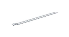
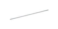
Protective tube for release cable
For floor springs with integrated closing sequence control
Protective tubing for release cable IS floor spring ID 059556
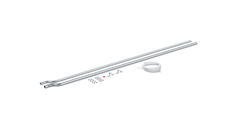
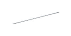
Door transmission cable Slimdrive EMD
For door leaf installation
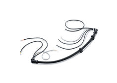
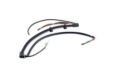
Door transmission cable
For door leaf installation
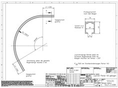
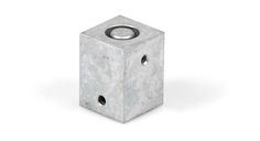
Drilling template for connecting tube
Round tube bottom
Round tube top

… tube 3. Bottom shoot tube 4. Tube guide 5. Push bar main unit 6. Slave unit 7. Push pad main unit 8. Shoot bush 9. Top trip guide 10. Top shoot end plug 11. Bottom shoot end plug 12. Adjustable bottom tube guide 13. Alternative floor plate 14. Vertical pullman catch cover 15. Vertical pullman latch 16 Horizontal pullman latch 17 Horizontal pullman catch cover IQ Bar 200 Series Hardware range Horizontal Pullman Catches IQ BAR 202 V A Push Bar … fixing screws. In case of using an outside access device (lever) pause the installation of the exit device and fit the lever before continuing with the installation. Refer to chapter “Lever 200 L - (OAD) C B A B C D E Unit Centre Height: between 930mm & 1130mm Oval Push Bar Length = B + 61mm Centre Latch Keep No. 0140 Distance from the edge of the last opening leaf to Tube Centre Line = minimum 50mm Rebated Double Door Keep No. 0144 B 22mm 10mm D 22mm E … Fixing and installation In case of using an outside access device (lever) pause the installation of the exit device and fit the lever before continuing with the installation. Refer to chapter Lever 200 L - (OAD) Step C: Preparing the shoot tubes. Rotate the mounting plate cam to the correct position (see template) and fit the main unit onto the mounting plate. XX Temporarily secure using one of the supplied M5 x … CSK screws. XX Measure accurately the bottom length (F) (from bottom spigot shoulder to floor / frame / face of keep), subtract 70mm and cut the plain end of the shorter tube to this length. XX Drive one of the threaded bushes into cut end of this tube. Bush must be driven in fully against the tube end. Screw in the bottom (plain) shoot end plug, leaving an 8mm Gap. XX Measure accurately the top length (G) (from top spigot shoulder to frame / face of keep), subtract 66mm and cut the plain end of the longer tube to this length. XX Drive the second threaded bush into cut end of this tube. Bush must be driven in fully against the tube end. Screw in the top (grooved) shoot end plug, leaving an 8mm gap. Step D: Fitting the shoot tubes, bottom guides & main operating unit. XX Remove the main operating unit from the door. XX Fit the previously prepared top & bottom shoot tubes (section B) onto the operating unit’s shoot spigots. Secure with the M5x10 cap head screws provided, with the screw heads facing the door face. XX Slide one standard (narrow) guide onto the top tube. XX Slide one standard (narrow) guide followed by the wide guide onto the bottom tube. XX Ensure the mounting plate cam is in the correct position (approximately … M5x8 CSK Screws provided. XX Locate the adjustable bottom tube guide the correct distance from the floor / frame (see diagram) and secure using the round headed screws provided. XX Locate the bottom middle guide equidistant on the tube (see diagram) and secure using the round headed screws provided. Ensuring the tube is vertical and the guides are in alignment. 10 IQ Bar 200 Series 3mm D 8mm GAP. K K C D E F G H I J K Adjustable Bottom Tube Guide Top Trip Guide Centre Latch Keep (IQ Bar 203 V A only) Bottom Shoot Tube Length Top Shoot Tube Length Top Trip Plate Easy Clean Socket Centre Latch (IQ Bar 203 V A only) Tube Guides IQ Bar 200 Series Step E: Fitting the top trip & top guide. XX Keeping the operating arm fully depressed. Locate the top trip guide device on the top shoot end plug. Use a 3mm thick spacer between the end of the top shoot and the underside of the frame / face of keep, to ensure that the shoot is fully withdrawn. Secure top trip guide to door using the round headed screws provided. XX Locate the top middle guide equidistant on the tube (see diagram) and secure using the round headed screws provided. Ensuring the tube is vertical and the guide and top trip are in alignment. XX Operate the exit device to ensure the top trip guide holds both shoots in the fully withdrawn position when the door is open. Step F: Fitting the keeps. XX Fit the top trip plate (H) morticed flush into the frame, with its narrow edge level with the door rebate (see diagram). Fix with the short (3/4” Long) countersunk screws provided. XX For solid floors fit the easy clean socket. Fit flush with the finished floor surface with its edge level with the inside door face. For wooden floors fit the alternative floor plate. Fit flush with the finished floor surface with the narrow edge level with the inside door face. Fixing and installation Step H: Testing the operation & fitting the sign. Test the unit to ensure that when the Push Bar/ Pad is operated the door opens immediately and swings freely. When the door is open the shoots are held fully withdrawn and when closed the shoots (and centre latch if present) engage fully in their keepers and hold the door securely closed. XX Fit the green self adhesive ‘Push Bar to Open’ / ‘Push Pad to Open’ sign onto the door positioned immediately above the Push Bar/Pad. Step I: Re-Handing the unit (If required) If either unit is handed the wrong way in error, please follow these instructions. XX Turn the unit upside down & pull out the mounting plate to remove it (if required) XX Slide a small flat bladed screwdriver into the smaller bit of the large aperture along the inside face of the steel chassis inserting it between the chassis and the handing cam (see the diagram). XX Gently lever the cam forward until it disengages from the arm spindle. XX Rotate the arm to re-hand the unit the required way (ensure the cam is fully engaged). XX IQ Bar 203 V A only XX With the door closed, position the centre latch keep (E) centred about the latch (J) with the flat face against the door face. Mark the positions of the fixing holes. Fix in place using the countersunk screws provided.“ XX Step G: Fitting the slave unit & oval cross bar. IQ Bar 202 V A & 203 V A only XX Temporarily fit the slave unit onto the mounting plate. XX Measure accurately the Arm Gap B (see diagram) add 61mm to this dimension and cut oval cross bar to this length. XX Remove slave unit from its mounting plate insert one end of oval cross bar into the main unit arm and the other into the slave unit arm. XX Refit the slave unit onto the mounting plate and secure using three of M5x8 CSK Screws provided. XX Secure the cross bar with the two of M4x6 set screws one in each arm. DO NOT OVER TIGHTEN 11 A Step A: Preparing the device XX Hand the main unit by removing the packaging and gently rotate the arm in the required direction (see diagram Step I) until it clicks. The unit is now handed. If handed incorrectly by mistake refer to Step I. XX Remove the mounting plate from the bottom of the main operating unit (pull out). BAR 203 H IQ Bar 203 H / IQ Pad 203 H A … fixing holes must be used and screw heads must not project above plate. IQ Bar 203 H only XX Hand the slave, same process as the main unit (Step A), but the opposite hand. XX Repeat the steps above to fit the slave unit mounting plate to the hinge side of the door. Fix this mounting plate to the door also using all six fixing screws. In case of using an outside access device (lever) pause the installation of the exit device and fit the lever before continuing with the installation. Refer to chapter Lever 200 L - (OAD) Step C: Positioning and fitting the pullman catches. XX Determine the height of the catches on the door. XX Place the template (DT-0074) on the door. Line up the appropriate lines. Mark the corresponding holes. XX Follow the instructions on the relevant template and drill the required holes. XX Remove the covers from the pullman units (2 cover screws). XX Fit each pullman catch using all three CSK screws provided. Note: to access two of the three screw holes; move the slide plate mechanism. Screw heads must be fully in the countersunk holes and not stand proud. 12 A Unit Centre Height: A = between 930mm & 1130mm B Oval Push Bar Length = B + 61mm C Centre Latch Keep D Top/Bottom Guide E Top/Bottom Keep F Bottom Shoot Tube Length = F + 7mm G Top Shoot Tube Length = G + 7mm H Pullman catch I Centre Latch IQ Bar 200 Series Step D: Preparing the shoot tubes. Rotate the mounting plate cam to the correct position (see template) and fit the main unit onto the mounting plate. XX Temporarily secure using one of the supplied M5 x … CSK screws. XX Measure accurately length (F), add 7mm and cut the plain end of the shorter tube to this length. XX Measure accurately length (G), add 7mm and cut the plain end of the longer tube to this length. XX Using the installation drift tube to prevent screw thread damage, drive the threaded shoot end plug into cut ends of both tubes. Plug must be driven in fully against the tube end. XX Re-fit the pullman catches (two cover screws, each) Step E: Fitting the shoot tubes, tube guides & main operating unit. XX Remove the main operating unit from the door. XX Screw the previously prepared shoot tubes (section C) fully into the pullman catches. XX Slide the tube guides onto the tubes (one on each tube) XX Ensure the mounting plate cam is in the correct position (see template). XX Place the main operating unit onto the mounting plate allowing the tubes to drift to one side. XX Operate the main operating unit mechanism to retract the shoot spigots. Guide the shoot tubes into position and slowly release the mechanism whilst guiding the spigots into the end of the tubes. XX Unscrew the tubes from the pullman catches until they almost contact the shoulder on the shoot spigots. Rotate the tubes back until the holes are facing the door. XX Pull the unit away from the door and secure the tubes using the M5x10 cap head screws provided. XX Fit unit back on the mounting plate and secure using three M5x8 CSK Screws. XX Locate the guides equidistant on the tubes (see diagram) and secure using the round headed screws provided. Ensuring the tubes are vertical and the guides are in alignment. Fixing and installation Step G: Fitting the slave unit & oval cross bar IQ Bar 203 H only XX Temporarily fit the slave unit onto the mounting plate. XX Measure accurately the arm gap (B) (see diagram) add 61mm to this dimension and cut Oval cross bar to this length. XX Remove slave unit from its mounting plate insert one end of oval cross bar into the main unit arm and the other into the slave unit arm. XX Refit the slave unit onto the mounting plate and secure using three of M5x8 CSK Screws provided XX Secure the cross bar with the two of M4x6 set screws one in each arm. DO NOT OVER TIGHTEN Step H: Testing the operation & fitting the sign. XX Test the unit to ensure that when the Push Bar/ Pad is operated the door opens immediately and swings freely. When the door is closed the pullman catches and centre latch engage fully in their keeps and hold the door securely closed. XX Fit the green self adhesive ‘Push Bar to Open’ / ‘Push Pad to Open’ sign onto the door positioned immediately above the Push Bar/Pad. Step I: Re-Handing the unit (If required) If either unit is handed the wrong way in error, please follow these instructions. XX Turn the unit upside down & pull out the mounting plate to remove it (if required) XX Slide a small flat bladed screwdriver into the smaller bit of the large aperture along the inside face of the steel chassis inserting it between the chassis and the handing cam (see the diagram). XX Gently lever the cam forward until it disengages from the arm spindle. XX Rotate the arm to re-hand the unit the required way (ensure the cam is fully engaged). Step F: Fitting the keeps. XX Position the included top/bottom keeps centred about the catch with the square face of the keep against the door (see diagram) and mark the holes. Fix in place using the countersunk screws provided. XX With the door closed, position the centre latch keep around the centre latch with the flat face against the door face. Mark the positions of the fixing holes. Fix in place using the countersunk screws provided. 13 Fixing and installation IQ Bar 202 V BAR 202 V … fixing screws. In case of using an outside access device (lever) pause the installation of the exit device and fit the lever before continuing with the installation. Refer to chapter Lever 200 L - (OAD) Step C: Preparing the shoot tubes. Rotate the mounting plate cam to the correct position (see template) and fit the main unit onto the mounting plate. XX Temporarily secure using one of the supplied M5 x … CSK screws. XX Measure accurately the bottom length (G), Subtract 111mm and cut the plain end of the 14 A B C D F E G H Unit Centre Height: A = between 930mm & 1130mm Oval Push Bar Length = B + 61mm Pullman catch Top/Bottom Guide Pullman Flush Door Keep No. 406A Top/Bottom Keep Bottom Shoot Tube Length = G - 111mm Top Shoot Tube Length = H - 111mm IQ Bar 200 Series XX XX shorter tube to this length. Measure accurately the top length H, Subtract 111mm and cut the plain end of the longer tube to this length. (For flush doors subtract 101mm) Using the installation drift tube to prevent screw thread damage, drive the threaded shoot end plug into cut ends of both tubes. Plug must be driven in fully against the tube end. Step D: Positioning and fitting the pullman catches. XX To establish the mounting position for the top and bottom pullman catchess first determine which type of keep/striker is required for the installation. Standard door/floor keep (included) or Pullman flush door keep No. 406A (F) (see diagram). XX Place the template (DT-0073) on the door. Line up the appropriate lines. Mark the corresponding holes. XX Follow the instructions on the relevant template and drill the required holes. XX Remove the covers from the pullman catchess (two cover screws) XX Fit the pullman catches, using CSK screws provided. Re-fit the covers. Step E: Fitting the shoot tubes, guides & main unit. XX Remove the main unit from the door. XX Screw the previously prepared shoot tubes (section B) fully into the pullman catches. XX Slide the guides onto the tubes (one on each tube) XX Ensure the mounting plate cam is in the correct position (see template). XX Place the main unit onto the mounting plate allowing the tubes to drift to one side. XX Operate the main unit mechanism to retract the shoot spigots. Guide the shoot tubes into position and slowly release the mechanism whilst guiding the spigots into the end of the tubes. XX Unscrew the tubes from the pullman catchess until they almost contact the shoulder on the shoot spigots. Rotate the tubes back until the holes are facing the door. XX Pull the unit away from the door and fix the tubes using the M5x10 cap head screws provided. XX Fit unit back on the mounting plate and secure using three M5x8 CSK Screws. XX Locate the guides equidistant on the tubes (see diagram) and secure using the round headed screws provided. Ensuring the tubes are vertical and the guides are in alignment. Fixing and installation screws provided. For flush door use keep No. 406A. Fit as shown and adjust with packers until the correct engagement is achieved. Step G: Fitting the slave unit & oval cross bar. XX Temporarily fit the slave unit to the mounting plate. XX Measure accurately the arm gap (B) (see diagram) add 61mm to this dimension and cut oval cross bar to this length. XX Remove slave unit from its mounting plate insert one end of oval cross bar into the main unit arm and the other into the slave unit arm. XX Refit the slave unit to the mounting plate and secure using three M5x8 CSK Screws provided. XX Secure the cross bar with the two of M4x6 set screws one in each arm. DO NOT OVER TIGHTEN Step H: Testing the operation & fitting the sign. XX Test the unit to ensure that when the Push Bar is operated the door opens immediately and swings freely and when the door is closed the pullman catches engage fully in the keeps and hold the door securely closed. XX Fit the green self adhesive ‘Push Bar to Open’ sign onto the door positioned immediately above the push bar. Step I: Re-Handing the unit (If required) If either unit is handed the wrong way in error, please follow these instructions. XX Turn the unit upside down & pull out the mounting plate to remove it (if required) XX Slide a small flat bladed screwdriver into the smaller bit of the large aperture along the inside face of the steel chassis inserting it between the chassis and the handing cam (see the diagram). XX Gently lever the cam forward until it disengages from the arm spindle. XX Rotate the arm to re-hand the unit the required way (ensure the cam is fully engaged). Step F: Fitting the keeps. XX Position the top/bottom keeps centred about the catch with the square face of the keep against the door (see diagram) and mark the holes. Fix in place using the countersunk 15 Fixing and installation … .1 Preparing the device Step A: Setting the outside access device’s lever for left or right hand opening doors XX First establish the lever handing direction required by checking its position on the door. XX Remove the label & packing and gently rotate the lever in the required direction, until you feel / hear the drive assembly engage. XX Continue to move the lever against the spring pressure until it’s just past the horizontal position. XX Hold the lever still and carefully insert the supplied lever set pin (11), through the hole in the back plate (4). Engage the thread and tighten. The lever is now set. Step B: Re-setting the outside access device’s lever if set the wrong way in error XX Operate the cylinder lock key in an anti-clockwise. Remove the key. XX Remove the backplate assembly (4) (4 screws). Taking care not to displace the drive spindle (6) from the lever boss (12). XX Remove the lever set pin (11) (if it has been fitted) XX Look inside the body. Locate the lever drive pin (10). Depress the spring loaded lever drive pin to disengage the lever (9) from, the sprung disc (8). XX Gently rotate the lever towards the correct position until the drive lever drive pin (10) reengages. Taking care not to rotate the ‘sprung disc’. XX Continue to move the lever against the spring pressure until it’s just past the horizontal position and the lever drive pin engages in the new position. Fit the lever set pin to retain the lever in its new position. XX Refit the backplate assembly (4) (4 screws). Line up the setting marks on the drive spindle (6) with those on the backplate assembly. Test the operation of the unit. OPTIONAL 3RD ADDITIONAL FIXING For added security a third mounting screw is provided for an additional outside access device fixing. However this extra screw is only hidden from view when used in conjunction with two & three point exit units (by the shoot tube), but is visible on the inside face of the door on single point (latch) versions. Fixing and installation … Drilling Template 0073 - Vertical Pullman Catches Fitting Template 27mm 39mm IN LINE WITH EDGE OF: FRAME / SILL / FLOOR THIS WAY UP FOR DOORS HUNG ON THE RIGHT HAND SIDE 3mm FOR SUPPLIED No.8 WOOD SCREW. TUBE CENTRE LINE MARK & DRILL … HOLES 25 IN LINE WITH EDGE OF SINGLE DOORFRAME TUBE CENTRE LINE MARK & DRILL