Search filter
58 results found
Integrated smoke switch control units
Security included – this is promised and delivered by the integrated smoke switch control units, which complete the security concept for the correspondingly equipped GEZE swing door drives.
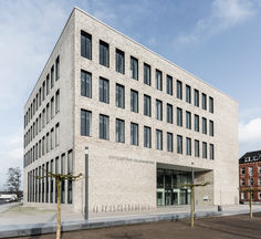
Window solutions for modernisation under historical preservation requirements
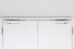
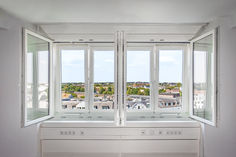
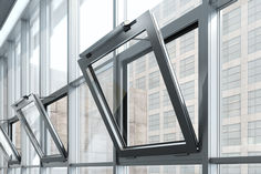
… stage to clarify specific requirements and guidelines. LEARN MORE ABOUT BUILDING RENOVATION The renovation of this historic building required not only technical expertise, but also careful coordination – so that all project partners can work closely together. The client's aim was to integrate innovative window solutions that preserve the charm of the tower blocks, while offering modern living comfort. Sören Eilers, Specification Sales Manager / Deputy Branch Officer at GEZE Nord Double casement windows as an innovative window solution that complies with historical preservation requirements Sören Eilers from GEZE and architect Martin Muus worked closely with the window and glass manufacturer during the planning process. © Jürgen Biniasch / GEZE GmbH Replacing the windows was unavoidable in order to improve the shading and ventilation concept and at the same time improve thermal insulation in summer and winter, sound proofing and user and working comfort. Under historical preservation requirements, the external appearance could not be changed, not even by sun protection. The idea: One of the oldest and most proven window types, the casement window, was reinterpreted by the architects Dipl. Ing. Muus and Dipl. Ing. Wilde, who were in charge of the project. To solve these challenges, the architects worked closely with window manufacturer Sehlmann Fensterbau GmbH, glass manufacturer Semcoglas Holding GmbH and the window drive specialists from EMT and GEZE at an early stage of the project – true to the motto "Achieving more together". Commitment and open communication with everyone involved enabled us to recognise challenges at an early stage and develop solutions together. This close and very cooperative partnership helped ensure the project went smoothly. Architects Dipl.-Ing. Muus and Dipl.-Ing. Wilde, MUUS & WILDE Architektenpartnerschaft Hamburg The solution: modern double casement windows that comply with historical preservation requirements Dennis Bredahl from Semcoglas Holding GmbH optimised the thermal and sound proofing of the double casement windows with special solar control and thermal insulation glazing. © Jürgen Biniasch / GEZE GmbH A double casement window consists of two window elements arranged one behind the other and mounted on a common frame. The advantage of this historic window concept: The air space between the two window elements serves as thermal insulation and sound proofing, as the staggered opening of the windows means that sound has to pass through the space between them and is thus significantly attenuated once again, even during ventilation. Our modern casement window solution uses high-quality solar control glass on the outside and thermal insulation glass on the inside, which significantly improves the insulation value and sound proofing – also increasing user comfort in the buildings. Thanks to the double glazing, double casement windows already offer much higher thermal and sound proofing compared to conventional windows. These properties were significantly improved by the use of high-quality solar control glazing and thermal insulation glass as so-called neutral glass and a special coating (Semco Klimaglas). Dennis Bredahl, Semcoglas Holding GmbH Window manufacturers Jan and Lasse Sehlmann implemented customised solutions that combine historical preservation and user requirements. © Jürgen Biniasch / GEZE GmbH Pleasant indoor climate thanks to integrated shading The new double casement windows are equipped with an integrated shading system. This consists of automatic composite blinds with 35 mm wide slats that run between the two window frames. This solution makes it possible to keep the rooms cool during the day, while at the same time ensuring natural ventilation through the outer window. The blinds can be operated independently for added convenience. This reduces costs for air conditioners and the offices are naturally ventilated. Modern casement window at the Grindel tower blocks in Hamburg. © Jürgen Biniasch / GEZE GmbH Safety and ease of use thanks to modern window drives For the outer window leaves, GEZE Slimchain drives were installed as a system solution in combination with the Power lock locking drive , which enables simple operation via push buttons in the room. The inner leaves of the double casement windows can still be opened manually. The Power lock locking drive ensures that a reliable lock is guaranteed, especially on the higher storeys, and even under heavy wind loads. As only the outer windows are motorised, no additional protection is required for power-operated windows in accordance with the Machinery Directive 2006/42/EC. The opening drives were integrated into the window frame in a concealed location, and the supply lines were routed in the construction joint. A unique feature: With their very slim and discreet appearance, the Slimchain window drives integrate perfectly into the structure – so that strict historical protection requirements are met. This means the well-insulated double casement windows with integrated shade control are a modern, comfortable and energy-efficient solution that simultaneously respects the architectural character of the building and complies with the strict historical preservation requirements. The technical expertise and the rapid involvement of all parties in the planning process enabled us to develop customised solutions that meet both high historical preservation requirements and the needs of building users. Jan and Lasse Sehlmann, window fitters at Sehlmann Fensterbau GmbH Achieving our goal together: successful project planning and coordination GEZE was already in close contact with all project participants in the early planning phases, which enabled smooth discussions and effective collaboration. This early involvement of all parties made it possible to identify potential challenges at an early stage and develop solutions together. In addition, GEZE supported project coordination through continuous cooperation with the partner company EMT. Contact with the architect and building services was also maintained during the implementation phase. This ongoing collaboration ensured that all aspects of the project were seamlessly integrated and that the implementation went smoothly. Modern history: the listed Grindel tower blocks The Grindel tower blocks in Hamburg's Eimsbüttel district were the first residential tower blocks built in Germany after 1945. They were highly modern and comfortable flats when they were built in the post-war period, and remain so today – with central heating, hot and cold running water and lifts. In addition, the flats are bright and flooded with light thanks to their orientation and windows, while remaining pleasantly shaded in summer. Today, the ensemble of twelve high-rise buildings and a park is historically preserved. A tip for visitors to Hamburg: in the centre of the Grindel tower blocks is the Eimsbüttel district office, which has become a real tourist attraction with its historic paternoster lift The Grindel tower blocks in Hamburg's Eimsbüttel district were the first residential tower blocks built in Germany after 1945. © Jürgen Biniasch / GEZE GmbH These consist of two window elements arranged one behind the other and mounted on a common frame. © Jürgen Biniasch / GEZE GmbH Double casement windows were used as a customised window solution for the Grindel tower blocks. © Jürgen Biniasch / GEZE GmbH Comprehensive support throughout the entire project life cycle Our experts support you throughout the entire project life cycle – from planning and project coordination to the certified assembly and initial acceptance of GEZE systems and regular maintenance, through to retrofitting and dismantling. Please get in touch with us – we will find customised solutions for your project. Go to the contact form Products used Opening drives Slimchain Chain drive in an attractive design with numerous possible applications in 24 V version Go to product Locking drives Power lock Locking drive in combination with Slimchain, Powerchain or E 250 NT Go to product Related topics Hotels & restaurants | Historic buildings | References | Accessibility | Fire protection | Building refurbishment | Hygiene | safety Historical preservation meets modern design at the Hotel Richer de Belleval The magnificent Hotel and restaurant Richer de Belleval in the French city of Montpellier impresses with a deft combination of historical beauty and modern comfort. GEZE's door systems were used in the successful restoration project. Read more Public buildings | References | Fire protection | Building refurbishment | ventilation | safety Retrofitting smart window systems with ease State-of-the-art window technology from GEZE ensures maximum safety at the Gare de Montreux railway station in Switzerland. The products also impress with their ability to be easily retrofitted and their customised design. Read more Sport/Culture | References | Accessibility | Building planning | ventilation | safety Smoke and heat extraction and ventilation systems in the OYM athletic centre Door and window systems from GEZE deliver peak performance in the OYM athletic centre in the fields of automated ventilation, fire protection, smoke and heat extraction and emergency exit protection. Read more

Why GEZE EZE BIM now?
… stage and deliver better coordinated projects. FAQs Our frequently asked questions (FAQs) about GEZE EZE BIM provide answers to questions commonly asked. Find out more Why GEZE EZE BIM now? Changing the game … creating better value for your clients. Produce more complete consistent information in the design stage and deliver better coordinated projects. Read more EZE BIM References Taking quality to a new level
… stage Processing recommendations, installation … Observe the instructions for mounting/installation, operation, maintenance and disassembly, provided by the manufacturer. Use stage Emissions to the environment No emissions to indoor air, water or soil are known. There may be VOC emissions. Reference service life (RSL) The RSL information was provided by the manufacturer. The RSL shall be specified under defined reference in-use conditions and shall refer to the declared technical and functional performance of the product within the building. It shall be established in accordance with any specific rules given in European product standards, or, if not available, in accordance with a c-PCR. It shall also take into account ISO 15686-1, -2, -7 and -8. Where European product standards or a c-PCR provide guidance on deriving the RSL, such guidance shall have priority. If it is not possible to determine the service life as the RSL in accordance with ISO 15686, the BBSR table “Nutzungsdauer von Bauteilen zur Lebenszyklusanalyse nach BNB” (service life of building components for life cycle assessment in accordance with the sustainable construction evaluation system) can be used. For further information and explanations refer to www.nachhaltigesbauen.de. For this EPD the following applies: For a “Cradle to gate with options” EPD with the modules C1-C4 and module D (A1-A3 + C + D and one or more additional modules from A4 to B7), the reference service life (RSL) can only be stated if the reference in-use conditions are specified. According to the manufacturer an optional service life of 25 years is specified for the products. The service life is dependent on the characteristics of the product and the in-use conditions. The in-use conditions described in the EPD are applicable, in particular the characteristics listed below: • Outdoor environment: no outdoor use permitted. • Indoor environment: certain factors (e.g. humidity, temperature) are known that may have a negative effect on the service life. The service life applies solely to the characteristics specified in this EPD or the corresponding references. The RSL does not reflect the actual life span, which is usually determined by the service life and the refurbishment of a building. It does not give any information on the useful life, warranty referring to performance characteristics or guarantees. EPD Electrical drives and pneumatic cylinders for SHEV and ventilation systems Declaration code: M-EPD-AZR-GB- … End-of-life stage Possible end-of-life stages The Electrical drives and pneumatic cylinders for SHEV and ventilation systems are shipped to central collection points. There the products are generally shredded and sorted into their original constituents. The endof-life stage depends on the site where the products are used and is therefore subject to the local regulations. Observe the locally applicable regulatory requirements. This EPD shows the end-of-life modules according to the market situation. Specific components of steel, copper, brass and plastics are recycled. Residual fractions are sent to landfill or partially thermally recycled. Disposal routes The LCA includes the average disposal routes. All life cycle scenarios are detailed in the Annex. EPD Electrical drives and pneumatic cylinders for SHEV and ventilation systems Declaration code: M-EPD-AZR-GB- … Product group: Building components for smoke and heat control system Scope / system boundaries The system boundaries refer to the supply of raw materials and purchased parts, production, use and end-of-life stage of Electrical drives and pneumatic cylinders for SHEV and ventilation systems. No additional data from pre-suppliers/subcontractors or other sites were taken into consideration. Cut-off criteria All the data that the company records, i.e. all commodities/input and raw materials used, the thermal energy used and electricity consumption, were taken into consideration. The boundaries cover only the product-relevant data. Building sections/parts of facilities that are not relevant to the manufacture of the products, were excluded. The transport distances of the raw materials, ancillary materials and packagings were taken into consideration. Transport to production plant using 40 t truck (Euro 0-6 mix), diesel, 27 t payload. As the transportation is exclusively handeled by forwarding agencies a 85 % capacity is used. In addition to the transport distances for pre-products, the transport distances for waste were also taken into consideration. The transport of waste in A3 was presented by the following standard scenario Transport to collection point using 40 t truck (Euro 0-6 mix), diesel, 27 t payload, 50 % capacity used, distance as provided by the manufacturer or 100 km (1) The criteria for the exclusion of inputs and outputs as set out in DIN EN 15804 are fulfilled. From the data analysis it can be assumed that the total of negligible processes per life cycle stage does not exceed … Inventory analysis Goal All material and energy flows are described below. The processes covered are presented as input and output parameters and refer to the declared unit. Life cycle stages The Annex shows the entire life cycle of Electrical drives and pneumatic cylinders for SHEV and ventilation systems. The “Product stage” (A1 – A3), “Construction process stage” (A4 – A5), “Use stage” (B2 – B5), “End-of-life stage” (C1 – C4) and the “Benefits and loads beyond the system boundaries” (D) are considered. Benefits The below benefits have been defined in accordance with DIN EN 15804: • Benefits from recycling • Benefits (thermal and electrical) from incineration Allocation of co-products The manufacture does not give rise to allocations. EPD Electrical drives and pneumatic cylinders for SHEV and ventilation systems Declaration code: M-EPD-AZR-GB- … Product group: Building components for smoke and heat control system Allocations for reuse, recycling and recovery If the products are recycled and recovered during the product stage (rejects) the components are shredded/broken if necessary and then sorted into their single constituents. This is done by various process plants, e.g. magnetic separators. The system boundaries were set following their disposal, reaching the end-of-waste state. Allocations beyond life cycle boundaries The use of recycled materials in the manufacturing process was based on the current market-specific situation. A recycling potential that reflects the economic value of the product after recycling (recyclate) was also taken into account. Secondary material stated as input into the production process, is calculated in module … Interpretation, LCA presentation and critical review Evaluation The environmental impacts of • Electrical drives • Pneumatic cylinders differ considerably. The differences result from the different pre-products and raw materials used / from the amount of relevant pre-products and raw materials used. Due to the different declared units the product groups can´t be compared directly. The environmental impacts during the manufacture of both product groups result mainly from the use of aluminium (also copper and steel in regards to electrical drives) or their upstream chains. Further important parameters in the use stage originate from the energy consumption of both product groups over the 50-year period. In scenario C4 only marginal consumptions arising from the physical pretreatment and management of the disposal site are expected. Allocation to individual products is almost impossible for site disposal. As regards the recycling of Electrical drives and pneumatic cylinders for SHEV and ventilation systems, for aluminium almost 30% of the environmental impacts arising during manufacture can be assigned as benefits to scenario D. As regards the recycling of pneumatic cylinders, for aluminium almost … The critical review of the LCA and the report took place in the course of verification of the EPD and was carried out by Patrick Wortner, MBA and Eng., Dipl.-Ing. (FH). General information regarding the EPD Comparability This EPD was prepared in accordance with DIN EN 15804 and is therefore only comparable to those EPDs that also comply with the requirements set out in DIN EN 15804. Any comparison must refer to the building context and the same boundary conditions of the various life cycle stages. For comparing EPDs of construction products, the rules set out in DIN EN 15804 (Clause … Annex B7 C1 C2 — — C4 D Reuse Recovery Recycling potential B6 Disposal B5 Waste processing Construction/installation process B4 Transport Transport B3 Deconstruction/demolition Manufacture B2 Operational water use Transport B1 Operational energy use A5 Modification/refurbishment A4 Replacement A3 Repair A2 Maintenance A1 Benefits and loads from beyond the system boundaries End-of-life stage Use stage* Use Product stage Construction process stage Raw material supply Description of life cycle scenarios for Electrical drives and pneumatic cylinders for SHEV and ventilation systems C3 * For the declared B modules, the calculation of the results is based on the specified RSL related to one year. Table 6: Overview of applied life cycle stages Calculation of the scenarios was based on a defined RSL (see Section … Use stage). The scenarios were based on information provided by the manufacturer. The scenarios were furthermore based on the research project “EPDs for transparent building components. (1) Note: The standard scenarios selected are presented in bold type. They were also used for calculating the indicators in the summary table. Included in the LCA — Not included in the LCA EPD Electrical drives and pneumatic cylinders for SHEV and ventilation systems Declaration code: M-EPD-AZR-GB- … ]. Ancillary materials, consumables, use of energy and water, waste, material losses and transport distances during repair are negligible. Since only one scenario is used, the results are shown in the relevant summary table. B4 Replacement No Scenario Description B4 Normal use and heavy use One replacement over a 25-year period (RSL)* *Assumptions for evaluation of possible environmental impacts; statements made do not constitute any guaranty or warranty of performance. The statements made in this EPD are only informative to allow evaluation at the construction works level. It is assumed that 1-time replacement will be necessary during the RSL of 25 years and the 50-year building service life. The results include the RSL and related to one year. For updated information refer to the respective instructions for assembly/installation, operation and maintenance from the manufacturer. The environmental impacts of the selected scenario result from the product, construction and disposal stages. Since only one scenario is used, the results are shown in the relevant summary table. EPD Electrical drives and pneumatic cylinders for SHEV and ventilation systems Declaration code: M-EPD-AZR-GB-
Climate-active façade improves energy efficiency at school
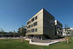
… stage regulation: 10°, 35° (slow and quiet ventilation) and 55° (rapid ventilation). Both teachers and students can adjust these settings. In addition, the system detects the wind direction, considering façade-dependent factors like wind pressure and wind suction, in addition to preventing draughts. Overflow elements ensure a controlled air exchange and are sound-insulated. User-friendly: automated ventilation + manual push buttons Ventilation in the building at the Grundäckergasse Middle School is controlled automatically, dependent upon CO2, temperature, usage, and the time. This solution allows for controlled natural ventilation, eliminating the need for manual ventilation by teachers. However, there are also operating elements teachers and students can use to intervene in the controls if necessary. These push buttons offer the option of manually opening or closing windows. That means the automated window ventilation system remains user-friendly and flexible. MORE ON AUTOMATED VENTILATION Safe design of automated windows Schools need to comply with high safety standards – after all, these are designed to protect the well-being of children. That is why it is important to consider that motorised windows are classified as machines under the Machinery Directive 2006/42/EC, and are to be protected accordingly. All motorised windows mounted under 2.5m in the school building at the Grundäckergasse Middle School were equipped with the GC 342 laser scanner and a safety module. This window safety system is on the inside and outside on the 1st floor in the patio area. MORE TIPS FOR WINDOW SAFETY Tip: identify hazardous areas around windows – with a free GEZE safety analysis Already during the planning stage, the GEZE safety analysis for power-operated windows serves as a guideline for the risk assessment that must be performed prior to commissioning – depending on the individual installation situation and user groups – in compliance with the Machinery Directive 2006/42/EC. TO THE SAFETY ANALYSIS Night cooling takes place via automatically controlled windows. © Sigrid Rauchdobler // GEZE GmbH Night-time ventilation saves energy Automatic night-time cooling contributes to energy efficiency at the Grundäckergasse Middle School. Windows automatically-controlled with Slimchain window drives dissipate heat generated during the day outside at night, lowering the room temperature in a targeted way during night-time hours. Night-time cooling is controlled via an on-site software, which handles not only regulation, but also visualisation. This way, operators and users can change settings. The system is controlled via the building management system (BMS), with both temporal and temperature-dependent factors taken into consideration. LEARN MORE ABOUT NIGHT-TIME COOLING Seamless integration into the building management system via BACnet and KNX Activation and feedback of the window drives via the building bus are handled by the IQ box KNX. Reliable status reports from each automated window ensure more efficiency in building monitoring. Other components like push buttons and sensors are connected through the integrated push button interface. This means that retrofitting and expansions can be completed easily as needed. Communication between the KNX and BACnet environment of the building management system (BMS) is smooth, since clear communication protocols have been defined between the systems. This guarantees efficient data transfer between the two systems. LEARN MORE ABOUT BUILDING AUTOMATION Your investment in myGEZE connectivity pays off © GEZE GmbH With our myGEZE connectivity amortisation calculator, we can determine how quickly your investment in intelligent building automation will pay off - through cost savings, improved safety and better air quality. Calculate the amortisation period for your building Overview of the advantages of climate-active façades Optimal indoor air quality through intelligent control of ventilation systems Adaptation of the ventilation, based on CO2 concentration, temperature, usage and time with three-stage regulation. Manual ventilation control possible via operating elements for teachers and students. Window safety, thanks to safety modules and GC 342 laser scanners. Wind direction taken into account to avoid draughts. Energy efficiency thanks to controlled air exchange and night-time cooling. Integration of BACnet sensors and KNX interface allows for efficient communication with the building management system. Innovative technologies help save energy and reduce CO2. Smart Building concept promotes sustainability and optimal building efficiency. MORE ON SMART BUILDING Forward-thinking: better sustainability and energy efficiency The climate-active façade on the Grundäckergasse Middle School in Vienna is an outstanding example of how to integrate smart technologies and more sustainable concepts in building, so as to meet future challenges in the areas of energy efficiency and sustainability. GEZE not only delivered the components necessary to do so, but also provided comprehensive advising and project management and programming services to make the project a success. Products used Laser scanner GC 342 Laser scanner for the protection of automatic doors and windows with integrated object and wall blanking Go to product Ventilation control units IQ box KNX Interface module for connecting the Slimchain, Powerchain and E 250 NT window drives in the KNX building bus Go to product Link arm 2-leaf TS 4000 IS Overhead door closer with link arm for double leaf doors with closing sequence control Go to product Slimdrive Slimdrive SL NT-FR Automatic linear sliding door system for escape and rescue routes with low overall height and clear design line Go to product Opening drives Slimchain Chain drive in an attractive design with numerous possible applications in 24 V version Go to product Related topics Topics | Energy efficiency | Automatic ventilation | Ventilation technology | Ventilation Automatic night-time back cooling Night-time window ventilation represents a particularly cost-efficient and energy-efficient method of air conditioning in buildings. GEZE supplies the right window technology for this. Read more Topics | Energy efficiency | Security | Smart Facade Smart façades Smart façades react actively and independently to their environment. The aim is to lower energy requirements to a minimum and to increase convenience and safety for the user. Read more
Professional window technology planning with GEZE
… stage. © Exorbitart / GEZE GmbH Planning window technology properly with GEZE Windows are playing an increasing range of roles in modern buildings. They improve the indoor climate by providing natural ventilation, play a crucial part in respect of energy efficiency, and ensure smoke and heat extraction in the event of fire. In addition, there are building-specific demands in terms of hygiene, comfort and safety. As a planner, it is easy to lose track of everything. As a partner for architects and planners, our experts are on hand to provide advice – from planning and individual project management, right through to commissioning. Window technology has to meet diverse demands Windows are playing an increasingly important role in buildings. Planners and architects thus face complex challenges when planning windows . In addition to the design aspects, they need innovative window functions that can satisfy the increasing demands placed on modern and liveable buildings. They must comply with legal regulations. This is where well-designed and safely-planned window systems come in. A variety of potential uses: Which window is right? Large windows are in high demand currently, and not just for design reasons. They flood rooms with plenty of natural daylight and give users a feeling of warmth and freedom. But modern windows must be capable of more: In addition to technical factors such as light penetration, heat, sound, and burglary protection, plus resistance to wind and rain, they also have to take on important functions such as ventilation or smoke and heat extraction. And there are additional criteria depending on whether it is roof windows or façade windows that are planned. The type of building and the user group also make a difference. These demands are often contradictory at first glance, making it hard to pick the right window solution. Legal regulations for window planning Not many people know: Power-operated or automated windows are machines according to the European Machinery Directive MRL 2006/42/EC. As a result, there are risk assessment requirements not just for manufacturers, but also for the planners, fitters and operators of these windows. In addition to certain technical specifications, they are subject to regular mandatory inspection. The machine manufacturer must ensure that a risk assessment is performed to determine the health and safety requirements applicable to the machine. This is the responsibility of the planner or the body issuing the invitation to tender. The risk assessment is performed according to the installation situation, the purpose of the building and the user group. For example, schools, child daycare centres and hospitals are assigned to the highest protection rating … if there is a risk of people being injured by power-operated windows. Window planning in modern buildings also involves complex demands. Window technology needs to be planned – there could otherwise be an impact on costs, as well as unnecessary stress Architects and planners need to think in detail about the use of windows in advance. What function will the window fulfil? Will it be used for natural ventilation or for smoke and heat extraction ? Or a combination of both? Which window type (side-hung, bottom-hung or top-hung window) is needed, and which opening direction corresponds to the installation situation? In addition, there are factors such as window dimensions, leaf weight, required opening widths (ventilation and smoke and heat extraction system), the intended use of the room and the user groups. If one or more of these parameters changes later in the process, time-consuming replanning or retro-fitting work may be necessary. For example, time and again the dimensions and weight of the window are specified incorrectly or change, so that the selected window drive no longer fits. It is also irritating if the power supply is too weak for the selected activation. Or if protective measures such as pinch protection were forgotten in the planning, and the operating the window is thus prohibited. For daily ventilation or in the event of fire, the range of window products extends from mechanical fitting systems for fanlights and smart drive systems for natural ventilation and exhaust, to complete solutions for preventive fire protection. It is therefore important to know in advance which functions the windows have to fulfil in a building. Find the right window drive Windows fulfil important functions in buildings Opening and locking system OL 350 EN, installed in the stairwell of an office building. © GEZE GmbH Natural ventilation thanks to intelligent window drives One of the key functions of windows is natural ventilation. Depending on the building, the specifications for indoor air are regulated differently. According to the German Energy Saving Ordinance (EnEV), in all instances “the minimum air exchange required for health and heating purposes must be ensured” . Architects must therefore take air quality and thermal comfort into account even at the building planning stage. This comprises the CO … to 4, we can offer you safe solutions. For example, our IQ box Safety uses sensors to stop the closing of a window as soon as a foreign object is detected. Our goal is to promote the development of liveable buildings. As a partner to architects and planners, we advise from an early stage on the possibilities of natural ventilation, the relevant safety aspects of power-operated windows and any necessary protective measures resulting from this. Dr Dominik Landerer, Product Manager at GEZE WinCalc window calculation programme GEZE WinCalc handles the complicated calculations when designing a window system: it's time-saving, user-friendly and convenient. This programme allows you to calculate manual as well as electric motor-driven ventilation windows, smoke and heat extraction system windows and SHEVs, and also helps you design the right smoke and heat extraction system control unit. The calculation programme handles the complex calculations for the system design of a window and provides all the drive solutions that can be used. GEZE customer portal login How GEZE supports you with your window planning GEZE offers a unique range of support services. In addition to our on-site project consultants, you can also take advantage of a wide range of tools and services. In our training centres , we offer you a comprehensive qualification programme for GEZE products, as well as seminars on specialist topics. Our WinCalc planning and calculation tool performs all the complicated calculations for the system design of a window On our YouTube channel, you can find comprehensive installation videos for our products Related topics Topics | Security | RWA | Fire protection Smoke and heat extraction Smoke and heat extraction (RWA) is part of preventive fire protection, and saves lives in the event of a fire. GEZE offers RWA solutions with intelligent drives for doors, windows and skylight domes. Read more Ventilation | GEZE Insights Natural ventilation to improve air quality Natural ventilation is more important than ever. In this interview, GEZE Head of Global Account Management, Karen Sum, outlines the methods and approaches we can use to enhance the fresh air supply and improve the air quality in buildings. Read more Product knowledge Find the right window drive Whether for natural ventilation or for smoke and heat extraction – GEZE offers a wide variety of window drives. We would be happy to help you make your selection. Read more
… stage Processing recommendations, installation … Observe the instructions for mounting/installation, operation, maintenance and disassembly, provided by the manufacturer. Use stage Emissions to the environment No emissions to indoor air, water or soil are known. There may be VOC emissions. Reference service life (RSL) The RSL information was provided by the manufacturer. The RSL shall be specified under defined reference in-use conditions and shall refer to the declared technical and functional performance of the product within the building. It shall be established in accordance with any specific rules given in European product standards, or, if not available, in accordance with a c-PCR. It shall also take into account ISO 15686-1, -2, -7 and -8. Where European product standards or a c-PCR provide guidance on deriving the RSL, such guidance shall have priority. If it is not possible to determine the service life as the RSL in accordance with ISO 15686, the BBSR table “Nutzungsdauer von Bauteilen zur Lebenszyklusanalyse nach BNB” (service life of building components for life cycle assessment in accordance with the sustainable construction evaluation system) can be used. For further information and explanations refer to www.nachhaltigesbauen.de. For this EPD the following applies: For a “Cradle to gate with options” EPD with the modules C1-C4 and module D (A1-A3 + C + D and one or more additional modules from A4 to B7), the reference service life (RSL) can only be stated if the reference in-use conditions are specified. According to the manufacturer an optional service life of 25 years is specified for the products. The service life is dependent on the characteristics of the product and the in-use conditions. The in-use conditions described in the EPD are applicable, in particular the characteristics listed below: • Outdoor environment: no outdoor use permitted. • Indoor environment: certain factors (e.g. humidity, temperature) are known that may have a negative effect on the service life. The service life applies solely to the characteristics specified in this EPD or the corresponding references. The RSL does not reflect the actual life span, which is usually determined by the service life and the refurbishment of a building. It does not give any information on the useful life, warranty referring to performance characteristics or guarantees. EPD Electrical control units, alert stations and pneumatic valves Declaration code: M-EPD-SVR-GB- … End-of-life stage Possible end-of-life stages The Electrical control units, alert stations and pneumatic valves are shipped to central collection points. There the products are generally shredded and sorted into their original constituents. The end-of-life stage depends on the site where the products are used and is therefore subject to the local regulations. Observe the locally applicable regulatory requirements. This EPD shows the end-of-life modules according to the market situation. Specific components of steel, copper, brass and plastics are recycled. Residual fractions are sent to landfill or partially thermally recycled. Disposal routes The LCA includes the average disposal routes. All life cycle scenarios are detailed in the Annex. EPD Electrical control units, alert stations and pneumatic valves Declaration code: M-EPD-SVR-GB- … Product group: Building components for smoke and heat control system Scope / system boundaries The system boundaries refer to the supply of raw materials and purchased parts, production, use and end-of-life stage of Electrical control units, alert stations and pneumatic valves. No additional data from pre-suppliers/subcontractors or other sites were taken into consideration. Cut-off criteria All the data that the company records, i.e. all commodities/input and raw materials used, the thermal energy used and electricity consumption, were taken into consideration. The boundaries cover only the product-relevant data. Building sections/parts of facilities that are not relevant to the manufacture of the products, were excluded. The transport distances of the raw materials, ancillary materials and packagings were taken into consideration. Transport to production plant using 40 t truck (Euro 0-6 mix), diesel, 27 t payload. As the transportation is exclusively handeled by forwarding agencies a 85 % capacity is used. In addition to the transport distances for pre-products, the transport distances for waste were also taken into consideration. The transport of waste in A3 was presented by the following standard scenario Transport to collection point using 40 t truck (Euro 0-6 mix), diesel, 27 t payload, 50 % capacity used, distance as provided by the manufacturer or 100 km (1) The criteria for the exclusion of inputs and outputs as set out in DIN EN 15804 are fulfilled. From the data analysis it can be assumed that the total of negligible processes per life cycle stage does not exceed … Inventory analysis Goal All material and energy flows are described below. The processes covered are presented as input and output parameters and refer to the declared unit. Life cycle stages The Annex shows the entire life cycle of Electrical control units, alert stations and pneumatic valves. The “Product stage” (A1 – A3), “Construction process stage” (A4 – A5), “Use stage” (B2 – B5), “End-oflife stage” (C1 – C4) and the “Benefits and loads beyond the system boundaries” (D) are considered. Benefits The below benefits have been defined in accordance with DIN EN 15804: • Benefits from recycling • Benefits (thermal and electrical) from incineration Allocation of co-products The manufacture does not give rise to allocations. EPD Electrical control units, alert stations and pneumatic valves Declaration code: M-EPD-SVR-GB- … Product group: Building components for smoke and heat control system Allocations for reuse, recycling and recovery If the products are recycled and recovered during the product stage (rejects) the components are shredded/broken if necessary and then sorted into their single constituents. This is done by various process plants, e.g. magnetic separators. The system boundaries were set following their disposal, reaching the end-of-waste state. Allocations beyond life cycle boundaries The use of recycled materials in the manufacturing process was based on the current market-specific situation. A recycling potential that reflects the economic value of the product after recycling (recyclate) was also taken into account. Secondary material stated as input into the production process, is calculated in module … Interpretation, LCA presentation and critical review Evaluation The environmental impacts of • Electrical control unit • Alert unit • Pneumatic valve differ considerably. The differences result from the different pre-products and raw materials used / from the amount of relevant pre-products and raw materials used. Due to the different declared units the product groups can´t be compared directly. The environmental impacts during the manufacture of electrical control units result mainly from the use of batteries. Further important parameters in the use stage originate from the energy consumption and the 12-time replacement of the batteries over the 50year period. The environmental impacts during the manufacture of alert stations result mainly from the use of aluminium, steel und powder coating or their upstream chains. The environmental impacts during the manufacture of pneumatic valves result mainly from the use of aluminium and stainless steel and their upstream chains. Furthermore causes the energy consumption for the manufacture of alert stations and pneumatic valves significant environmental impacts. In scenario C4 only marginal consumptions arising from the physical pretreatment and management of the disposal site are expected. Allocation to individual products is almost impossible for site disposal. As regards the recycling of Electrical control units for batteries around 27% of the environmental impacts arising during manufacture can be assigned as benefits to scenario D. For alert stations and pneumatic valves the recycling of the contained metals results in about 20 % resp. 25 % of the environmental impacts assigned as benefits to scenario D. Some of the LCA results differ considerably from those presented in the EPD prepared five years ago. The differences are due to differences in normative regulations, the application of uncertainty penalties, the use of other, more suitable “LCA for Experts” datasets, modification of the underlying “LCA for Experts” data and a new data collection at a different set of participating member companies of the VFE. The charts below show the distribution of the main environmental impacts. The values obtained from the LCA calculation are suitable for the certification of buildings. EPD Electrical control units, alert stations and pneumatic valves Declaration code: M-EPD-SVR-GB- … General information regarding the EPD Comparability This EPD was prepared in accordance with DIN EN 15804 and is therefore only comparable to those EPDs that also comply with the requirements set out in DIN EN 15804. Any comparison must refer to the building context and the same boundary conditions of the various life cycle stages. For comparing EPDs of construction products, the rules set out in DIN EN 15804 (Clause … Annex B7 C1 C2 — — C4 D Reuse Recovery Recycling potential B6 Disposal B5 Waste processing Construction/installation process B4 Transport Transport B3 Deconstruction/demolition Manufacture B2 Operational water use Transport B1 Operational energy use A5 Modification/refurbishment A4 Replacement A3 Repair A2 Maintenance A1 Benefits and loads from beyond the system boundaries End-of-life stage Use stage* Use Product stage Construction process stage Raw material supply Description of life cycle scenarios for Electrical control units, alert stations and pneumatic valves C3 * For the declared B modules, the calculation of the results is based on the specified RSL related to one year. Table 6: Overview of applied life cycle stages Calculation of the scenarios was based on a defined RSL (see Section … Use stage). The scenarios were based on information provided by the manufacturer. The scenarios were furthermore based on the research project “EPDs for transparent building components. (1) Note: The standard scenarios selected are presented in bold type. They were also used for calculating the indicators in the summary table. Included in the LCA — Not included in the LCA EPD Electrical control units, alert stations and pneumatic valves Declaration code: M-EPD-SVR-GB- … ]. Ancillary materials, consumables, use of energy and water, waste, material losses and transport distances during repair are negligible. Since only one scenario is used, the results are shown in the relevant summary table. B4 Replacement No Scenario Description B4 Normal use and heavy use One replacement over a 25-year period (RSL)* *Assumptions for evaluation of possible environmental impacts; statements made do not constitute any guaranty or warranty of performance. The statements made in this EPD are only informative to allow evaluation at the construction works level. It is assumed that 1-time replacement will be necessary during the RSL of 25 years and the 50-year building service life. The results include the RSL and related to one year. For updated information refer to the respective instructions for assembly/installation, operation and maintenance from the manufacturer. The environmental impacts of the selected scenario result from the product, construction and disposal stages. Since only one scenario is used, the results are shown in the relevant summary table. EPD Electrical control units, alert stations and pneumatic valves Declaration code: M-EPD-SVR-GB-
… stages B1-B7. The End-of-Life (EoL) stages are also considered. The transportation to the EoL disposal site is taken into account in module C2. Module C4 covers the disposal of the glass door gear. Module C3 covers the recycling of the individual elements according to European averages, with the remaining waste divided between incineration and landfill. The same assumption as for waste to recycling in A3 is used here. For end-of-life modules (C1 to C4) the system boundaries from the XP P01-064/CN standard have been followed, see annex H.2 and H.6 of this document for figures and further details. In practice, the end-of-life has been modelled as follows: - When a material is sent to recycling generic transport and electric consumption of a shredder is taken into account (corresponding to the process “Grinding, metals”). Only then is the material considered to have attained the “end-of-waste” state. - Each type of waste is modelled as transport to the treatment site over a distance of 30 km (source: FD P01-015). Parts sent for recycling include an electricity consumption (grinding) and a flow (“Materials for recycling, unspecified”). Four scenarios for the end-of-life of the products have been declared for this EPD: 1. 100% of the product going to landfill 2. 100% of the product going to incineration 3. 100% of the product going to recycling 4. Mixed scenario consisting of the previous three scenarios, with values depending on the amount of waste going for recycling. Module D has not been declared. … "Description of the system boundary", the declared modules are indicated with an "X"; all modules that are not declared within the EPD but where additional data are available are indicated with "MND". Those data can also be used for building assessment scenarios. The values are declared with three valid digits in exponential form. DESCRIPTION OF THE SYSTEM BOUNDARY (X = INCLUDED IN LCA; MND = MODULE NOT DECLARED) BENEFITS AND LOADS BEYOND THE SYSTEM BOUNDARIES Replacement Refurbishment Operational energy use B1 B2 B3 B4 B5 B6 X X X X X ReuseRecoveryRecyclingpotential Repair A5 Disposal Maintenance A4 Waste processing Use A3 Transport Assembly A2 De-construction demolition Transport from the gate to the site A1 Operational water use Manufacturing END OF LIFE STAGE Transport USE STAGE Raw material supply PRODUCT STAGE CONSTRUCTI ON PROCESS STAGE B7 C1 C2 C3 C4 D X X X X MND MND MND MND MND MND MND MND RESULTS OF THE LCA - ENVIRONMENTAL IMPACT: … Environmental Product Declaration ARGE – Glass door gear - scenario 1: the product is considered to be 100% incinerated - scenario 2: the product is considered to be 100% landfilled - scenario 3: the product is considered to be 100% recycled 6. LCA: Interpretation This chapter contains an interpretation of the Life Cycle Impact Assessment categories. When expressed as a percentage, the impact refers to its magnitude expressed as a percentage of total product impact across all modules, with the exception of module D. The majority of the product’s impacts are due to the extraction and supply of raw materials (A1). The manufacturing stage (A3) represents a significant percentage of the impacts, as does the transportation of the finished product (A4), especially for the indicator concerning ozone depletion. 7. Requisite evidence No testing results are required by the PCR part B. 8. References ISO 14040 ISO 14040:2006-10, Environmental management – Life cycle assessment – Principles and framework (ISO 14040:2006).” German and English version EN ISO 14040:2006 DIN EN ISO 14044 DIN EN ISO 14044:2006-10, Environmental Management — Life Cycle Assessment Requirements and Instructions (ISO 14044:2006); German and English version EN ISO 14044:2000 CEN/TR 15941 CEN/TR 15941:2010-03, Sustainability of construction works —Environmental Product Declarations — Methodology for selection and use of generic data; German version CEN/TR 15941:2010
… stages B1-B7. The End-of-Life (EoL) stages are also considered. The transportation to the EoL disposal site is taken into account in module C2. Module C4 covers the disposal of the sliding door gear. Module C3 covers the recycling of the individual elements according to European averages, with the remaining waste divided between incineration and landfill. The same assumption as for waste to recycling in A3 is used here. For end of life modules (C1 to C4) the system boundaries from the XP P01-064/CN standard have been followed, see annex H.2 and H.6 of this document for figures and further details. In practice, the end of life has been modelled as follows: - When a material is sent for recycling generic transport and electric consumption of a shredder is taken into account (corresponding to the process “Grinding, metals”). Only then, is the material considered to have attained the “end of waste” state. - Each type of waste is modelled as a transport to the treatment site with a distance of 30 km (source: FD P01-015). Parts sent for recycling include an electricity consumption (grinding) and a flow (“Materials for recycling, unspecified”). Four scenarios for the end of life of the products have been declared for this EPD: 1. 100% of the product going in landfill 2. 100% of the product going in incineration … "Description of the system boundary", the declared modules are indicated with an "X"; all modules that are not declared within the EPD but where additional data are available are indicated with "MND". Those data can also be used for building assessment scenarios. The values are declared with three valid digits in exponential form. DESCRIPTION OF THE SYSTEM BOUNDARY (X = INCLUDED IN LCA; MND = MODULE NOT DECLARED) BENEFITS AND LOADS BEYOND THE SYSTEM BOUNDARIES Replacement Refurbishment Operational energy use B1 B2 B3 B4 B5 B6 X X X X X ReuseRecoveryRecyclingpotential Repair A5 Disposal Maintenance A4 Waste processing Use A3 Transport Assembly A2 De-construction demolition Transport from the gate to the site A1 Operational water use Manufacturing END OF LIFE STAGE Transport USE STAGE Raw material supply PRODUCT STAGE CONSTRUCTI ON PROCESS STAGE B7 C1 C2 C3 C4 D X X X X MND MND MND MND MND MND MND MND RESULTS OF THE LCA - ENVIRONMENTAL IMPACT/ sliding door gear unit Param eter Unit A1-A3 A4 A5 C1 C2 C2/1 C2/2 C2/3 C3 C3/1 C3/2 C3/3 C4 C4/1 C4/2 C4/3 9.01E+ 0.00E+ 0.00E+ 0.00E+ 0.00E+ GWP [kg CO2-Eq.] 5.89E-1 1.36E-2 5.05E-3 5.05E-3 5.05E-3 5.05E-3 4.85E-3 8.66E-3 1.27E-2 5.23E-1 4.97E-1 … Environmental Product Declaration ARGE – Sliding door gear Other end of life scenarios have been calculated in order to build specific end of life scenario at the building level: - scenario 1: the product is considered to be 100% incinerated - scenario 2: the product is considered to be 100% landfilled - scenario 3: the product is considered to be 100% recycled 6. LCA: Interpretation This chapter contains an interpretation of the Life Cycle Impact Assessment categories. When expressed as a percentage, the impact refers to its magnitude expressed as a percentage of total product impact across all modules, with the exception of module D. The majority of the product’s impacts are due to the extraction and supply of raw materials (A1). The manufacturing stage (A3) represents a significant percentage of the impacts –notably for the depletion of non-fossil abiotic resources due to the zinc coating process and the wasted aluminium - as does the transportation of the finished product (A4), especially for the indicator concerning ozone depletion. The results are conservative as complying with the composition given in section
Building Information Modelling (BIM)
… stages, sent to the authorities, and then revised once more. Creating cost calculations and coordinating individual trade processes on the construction site are also key tasks. But with building projects becoming increasingly complex, these processes often don’t run smoothly., because There are numerous interdependent links and changing relations which need to be continuously taken into account. Integrated planning with BIM BIM, or building data modelling, connects everyone involved on one platform and reduces the number of coordination steps. BIM represents a new integrated and digital building planning system which can be seen as a gigantic database. As part of this, all of the objects which are specific to the building (for example masonry, doors, windows, etc. as well as building technology) are digitally recorded, combined and networked in a unique 3D model on which all participants work. The database also contains all relevant information about the materials and their life span, sound permeability or fire protection and, most importantly, costs. Buildings can thus be designed, modelled, optimised and simulated with the help of BIM. The aim is to implement construction projects more cheaply and simply, and with fewer delays. Additionally, models are not only used for construction: they also make subsequent operation safer, more comfortable and more efficient. Our BIM expert Günther Weizenhöfer in an interview on "Building planning with BIM" High planning quality The key advantage of BIM is that all participants - architects and planners, general contractors and builders/operators - can virtually inspect the construction project as a model in the planning phase. Errors and inconsistencies can be identified and quickly be amended at the model stage, which means that the quality, and more importantly the safety, of the planning are greatly improved. Additionally, construction companies can select materials and contractors at an early stage based on the information and proposals stored in BIM. Use of BIM is gaining ground for public sector construction projects in Europe The UK, the Netherlands, Denmark, Finland and Norway also prescribe the use of BIM for publicly funded construction projects. In Germany, the Ministry for Transport and Digital Infrastructure (BMVI) wants to use BIM for all new planning projects from 2020. Advantages of virtual construction with BIM Better exchange of information among all stakeholders Increased productivity Earlier error detection and rectification Greater planning and cost security BIM objects increase planning security and reduce error rates Digital building models are the core element of the BIM method. These consist of individual BIM objects, i.e. the digital equivalent of real construction products. They are based on structured data which enable product comparisons, for example dimensions, weights, technical product information and manufacturer data such as available variants, order dates, prices, delivery times, installation or maintenance information, etc. If BIM objects are built into BIM building models, this simplifies the invitation for tenders, cost estimation, calculation and simulation in the planning phase. In the execution phase, this supports ordering, delivery, execution itself and assembly. What's more, it simplifies building management in the operation phase. BIM objects can rationalise work processes, minimise sources of error and ensure increasing digitalisation in construction. Günther Weizenhöfer, Architect and Team Leader of Planning Seminars at GEZE Design and deliver construction projects quickly and securely using BIM door objects All the doors in a building can be planned extremely easily using GEZE BIM objects. In contrast to many other providers, GEZE always offers a whole door as a BIM object, so that the door can be considered with all its components. These multifunctional doors can be used to depict all swing doors, sliding doors and revolving doors. The GEZE BIM objects are free of charge for Autodesk Revit, Graphisoft Archicad and Nemetschek Allplan. Learn more about BIM Door Objects and download them Terminology BIM Glossary A common information base is necessary so that all project participants can work with BIM effectively. Building Information Modeling thrives on a transparent, shared knowledge platform. Here you will find the most important BIM terms, so that you will be able to start a successful cooperation. If you have any questions, please don’t hesitate to contact our team of experts. Terms A to B Big BIM Big BIM refers to the continuous application of BIM throughout the complete life cycle of a building, integrating all trades. This means all designs and calculations are implemented into a shared software environment. BIM Collaboration Format (BCF) The BIM collaboration format is an open exchange format enabling straightforward communication among all contributing parties in the BIM process. In an IFC model (please see Industry Foundation Classes), clashes or other issues can be localized and tagged with comments. BCF files can be read and edited by common model checkers. Some CAD systems provide BCF format enabled mark-up tools. BIM Execution Plan (BEP) The BIM Execution Plan is an element of the legal framework for BIM. It describes how employer’s information requirements (please see EIR) are fulfilled. Essential content of the BEP includes role assignment, definition of work flows, and specification of hard- and software to be used in the process. BIM level