Search filter
32 results found
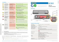
… ORANGE LED flashes every second. The sensor goes into security mode. … The ORANGE LED flashes … If orange LED flashes again, replace sensor. … The ORANGE LED flashes … The ORANGE LED flashes … Launch a new assisted setup. R GC 333 C Z I E RUNG FI TI N A C Z E W I T H E C N E N A B L E S O A C C R D A Other use of the device is outside the permitted purpose and can not be guaranteed by the manufacturer. The manufacturer cannot be held responsible for incorrect installations or inappropriate adjustments of the sensor. Safety sensor for automatic revolving doors DESCRIPTION The ORANGE LED flashes … Adapt background if necessary (floor is too reflective). The ORANGE LED is on. The sensor encounters a memory problem. … If orange LED lights up again, replace sensor. The RED LED flashes quickly after an assisted setup. The sensor sees the door during the assisted setup.
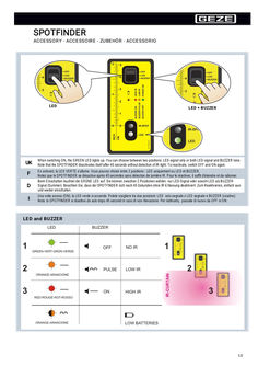
… ORANGE LED lights up and/or until the BUZZER beeps. Pour un positionnement correct des rideaux de sécurité, mettez le SPOTFINDER par terre et contre la porte comme ci-dessus. Ajustez les rideaux de sécurité jusqu'à ce que la LED ORANGE s'allume et/ou jusqu'au signal du BUZZER. Um die Lichtvorhänge korrekt zu positionieren, legen Sie den SPOTFINDER flach auf den Boden und gegen die Tür wie oben abgebildet. Bewegen Sie die Lichtvorhänge bis die ORANGE LED aufleuchtet und/oder bis der BUZZER-Ton ertönt. Per posizionare correttamente la tenda di sicurezza, mettere lo Spotfinder a terra e contro la porta come indicato. La regolazione della tenda di sicurezza sarà completata quando la LED ARANCIONE si accenderà e/o il cicalino suonerà. Replacing batteries ORANGE LED FLASHING ALKALINE AAA – LR03 Tips UK F D

… orange terminal field. This is the as-supplied state. If a BMA or GMA system is connected, the 2K resistor at the emergency unlocking input of the TZ300 (terminals … Colour Former designation to DIN 47002 New designation to DIN IEC 757 Colour Former designation to DIN 47002 New designation to DIN IEC 757 Black Brown Red Orange Yellow Green sw br rt or ge gn BK BN RD OG YE GN Blue Violet Grey White Pink Turquoise bl vi gr ws rs tk BU VT GY WH PK TQ Current consumption When connecting external devices, observe the overall power consumption. àà Output rating for external devices through standard PSU: àà Flush-mounted version (NET220): 24 V DC, max. 350 mA àà Surface-mounted version (NT19.2-24): 24 V DC, max. 650 mA àà Output rating for external devices through external PSU (Net24-5, Logo): … Wiring diagram Door control units Programming interface orange Door LED blue Latch LED Emergency button LED red Tamper switch Buzzer Alarm LEDs … 3 orange terminal field … .4 SECULOGIC TZ300 TZ300SN, TZ300S: Door monitor without locking element For use, for example, as door monitor Function: The door can be opened at any time through the panic handle. Opening the door without authorization triggers the door alarm, which, in turn, triggers a visual and acoustic alarm through the built-in signal generators. The door alarm remains active until the door is closed again and the alarm is reset with the built-in key switch or through the Short-term release input. Authorized access is possible with short-term release function or by permanently unlocking the door. X102 (blue) X100 (red) 24 V DC Lock SCT, KZF, acknowledge Unlock SCT, acknowledge Tamper GEZE SCT320 Key switch X102 or X103 Ribbon cable Connection to TST300 X103 TST300 Plug for GEZE key switch X100 (red terminal strip) Power supply unit Screw terminal Supply GND 24 V DC supply Relay card RP220 Nr. 102355 X101 (orange terminal strip) Locking + Locking Door locked Door contact 24 V DC Door closed 24 V DC Brief unlocking input Emergency unlocking input 24 V DC Temporary unlocking through: - External key switch - Access control - Cylinder contact - Button, etc. Floating NO contact required Caution: Order of terminals not as on terminal strip X102 (blue terminal strip) Alarm output max. … .1 Holding magnet MA500 (single-leaf doors) TST300 - X101 (orange terminal strip) Locking + Locking Door locked 24 V DC Door closed 5) Door contact 24 V DC … .2 Holding magnet MA500 (two-leaf doors) TST300 – X101 (orange terminal strip) Locking + Locking Door locked 24 V DC Door closed Door contact 26 Door contact SECULOGIC TZ300 … .3 Wiring diagram Emergency door opener TYP331U DIN right/left (single-leaf doors) X101 (orange terminal strip) FTÖ331U Locking + … .4 AKRR RR Caution: Sever red wire jumper (1–7) behind the terminal field of the FTÖ331U. Emergency door opener TYP331U DIN right/left (two-leaf doors) X101 (orange terminal strip) A B FTÖ331U FTÖ331U … .5 AKRR RR AKRR RR Caution: Sever red wire jumper (1–7) behind the terminal field of the FTÖ331U. Emergency door opener TYP331 DIN right/left (single-leaf doors) FTÖ331 DIN right X101 (orange terminal strip) FTÖ331 DIN left Locking + … .6 SECULOGIC TZ300 Emergency door opener TYP331 DIN right (two-leaf doors) X101 (orange terminal strip) A B Locking + … NC RD NO GN COM BU NC AKRR RR Emergency door opener TYP332 (1-leaf doors) X101 (orange terminal strip) Locking + Locking Door closed 24 V DC 24 V DC Door locked Relay card RP220 No. 102355 28 RR Emergency door opener TYP331 DIN left (two-leaf doors) X101 (orange terminal strip) … .2 Key switch SCT220 to short-term release orange terminal strip 24 V DC COM Brief unlocking input Closed on right Closed on left No. 115937, UP Jung AS500, WW No. 094170, UP Jung LS990, stainless steel No. 094012, UP GIRA E2, pure white … .3 Key switch SCT221/SCT to short-term release (orange terminal strip) 24 V DC Brief unlocking input SCT No. 117996 + 024467 UP AS500 SCT No. 117996 + 024467 + 120503 AP AS500 SCT221 No. 054240 + 024467 without PHZ UP SCT221 No. 054532 + 024467 without PHZ AP SCT221 No. 054245 + 024467 with PHZ UP SCT221 No. 054533 + 024467 with PHZ AP No. 094170, UP Jung LS990, stainless steel No. 094012, UP GIRA E2, pure white 29 Wiring diagram … .6 Wiring diagram Key switch with indicator SCT222 For connecting the SCT222, relay card RP220 is required in addition. red terminal strip Power supply unit Screw terminal Supply GND 24 V DC supply orange terminal strip Locking + Locking Door locked 24 V DC Door closed 24 V DC Door contact Brief unlocking input Emergency unlocking input 24 V DC Caution: Sever red wire jumper (1–7) behind terminal field of FTÖ331U Caution: Order of terminals not as on terminal strip Relay card RP220 Nr. 102355 blue terminal strip 24 V DC Alarm output max. … .1 Numerical code lock Toplock CTI, CTI B X102 (blue) or X100 (red) X101 (orange terminal strip) Brief unlocking input … .2 Numerical codelock Toplock CTS V, CTS BV Number codelock Toplock CTS V, CTS BV (orange terminal strip) 24 V DC Brief unlocking input 32 Evaluation unit SECULOGIC TZ300 … .3 Wiring diagram Access control Single-door control unit GCDU100 Door control unit GCDU200 (orange terminal strip) 24 V DC Brief unlocking input Optionally the GCDU100 can be supplied with power through the TZ300. Observe total power consumption! X100 (red terminal strip) Supply GND 24 V DC supply … Timer (orange terminal strip) 24 V DC Brief unlocking input Floating NO contact The door control unit is temporarily unlocked for the duration of the contact. 33 Wiring diagram SECULOGIC TZ300 … .1 IQ Lock EM power from TZ300 For connecting the IQ Lock EM, relay card RP220 is required in addition. X100 (red terminal strip) Power supply unit Screw terminal Supply GND 24 V DC supply X101 (orange terminal strip) Locking + Locking Door locked 24 V DC Door closed 24 V DC Door contact Brief unlocking input Emergency unlocking input 24 V DC Caution: Sever red wire jumper (1–7) behind terminal field of FTÖ331U Caution: Order of terminals not as on terminal strip Relay card RP220 Nr. 102355 Lock connection cable X102 (blue terminal strip) red wire Magnet + black wire Magnet - red/blue wire COM cylinder contact grey/pink wire NO cylinder contact Temporary unlocking through: - External key switch - Access control - Button, etc. Floating NO contact required Function: When the TZ300 is locked, the outer lever handle of the IQ Lock EM is disengaged. When the TZ300 is temporarily or permanently unlocked, the outer lever handle is engaged. Option 1: When the cylinder contact of IQ Lock is connected to the Temporary Unlocking input, cylinder operation through the key triggers temporary unlocking. At the same time, the TZ300 engages the outer lever handle. *) Observe total power consumption of the TZ300. If necessary, use a separate power supply unit. 34 SECULOGIC TZ300
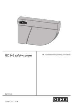
… orange. Confirming the setting XX Press the push button for longer than … .5 Checking a value x orange x = Number of flashes = Parameter value Example: 2x green … seconds to disable the service mode. The sensor does Inverted power not respond when supply switched on Faulty cable The sensor does not respond after power-on 32 GC 342 safety sensor Fault messages and troubleshooting LED Display Effect Cause Elimination – A parameter cannot be set using the remote control Wrong DIP switch position XX Switch the corresponding DIP switch to ON. The remote control does not react The sensor is protected by an access code XX Enter the access code. The orange LED lights up permanently The sensor has a memory problem XX Send the sensor back to the manufacturer for checking. The orange LED flashes quickly DIP switch setting expects confirmation XX Keep the push button pressed to confirm the DIP switch settings. … The orange LED flashes 1× every … seconds The sensor has detected an internal error Switch the sensor power supply off/on. If the orange LED lights up again: XX Replace the sensor. Voltage supply too low or too high XX … The orange LED flashes 2× every … 4 GC 342 safety sensor Effect Cause Elimination The orange LED flashes 3× every … seconds if the door connection cable BS/BGS has definitely been removed. The orange LED flashes 4× every … Fault messages and troubleshooting Effect Cause Elimination The orange LED flashes 5× every … The orange LED flashes 6× every … seconds Check whether all the teach-in requirements were met. Teach-in again with the door closed. Change the inclination angle. Teach-in again with the door closed. Set the field dimensions using the remote control, press and trigger a door opening. Permanently faulty door position measure data Check whether all three fixing screws have been tightened. XX Teach-in again with the door closed. If the orange LED lights up again: XX Contact GEZE Service. Occasional faulty door position measure data XX XX XX XX XX Check whether all three fixing screws have been tightened. Move out of the detection area and wait until the door closes. In closed position, switch the sensor power supply off and on again. Teach-in again with the door closed. 35 Technical data 16 GC 342 safety sensor Technical data Technology Laser scanner, time-of-flight measurement Detection mode Presence Max. detection area
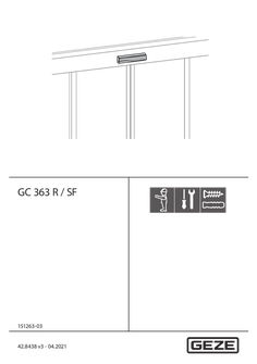
… ORANGE LED flashes … x The sensor has detected an internal error. X Replace the sensor. E2 The ORANGE LED flashes … x The power supply is too low or too high. X Check the power supply (in the LCD diagnosis menu). Check the wiring. The sensor is receiving too little AIR energy. X E4 The ORANGE LED flashes … x X X X E5 The ORANGE LED flashes … or 3. E6 GC 363 SF only: The ORANGE LED flashes … x The radar output is defective. X Replace the sensor. E7 GC 363 SF only: The ORANGE LED flashes … x Interference of the internal radar test. X X Change the radar angle. Change the radar antenna. Replace the sensor if the ORANGE LED continues to flash. E8 The ORANGE LED flashes … x The AIR energy transmitter is defective. X Replace the sensor. E9 The ORANGE LED flashes … x The internal radar reference is incorrect. X Replace the sensor. – The ORANGE LED is on The sensor has a memory problem. X Switch the power supply off and on. Replace the sensor if the ORANGE LED lights up again. X X 30 GC 363 R / SF Fault messages and troubleshooting LCD display Effect Cause Elimination – The RED LED flashes quickly after teach-in with door movement The sensor senses the door during teach-in with door movement. X X X – – The RED LED lights up sporadically The GREEN LED lights up sporadically The sensor is vibrating. X X X Start teach-in with door movement and change the AIR angle. Elements in the environment are interfering with the sensor. X Increase AIR immunity filter to 3. Select default setting

… ORANGE LED flashes … x The sensor has detected an internal error. X The power supply is too low or too high. X E2 The ORANGE LED flashes … x X X E4 The ORANGE LED flashes … x The sensor is receiving too little AIR energy. X X X E5 The ORANGE LED flashes … x The sensor is receiving too much AIR energy. External elements are interfering with the sensor. X X X Switch the power supply off and on. Replace the sensor if the ORANGE LED continues to flash. Check the power supply (in the LCD diagnosis menu). Check the wiring. Reduce the AIR angle. Increase the AIR immunity filter (values > … or 3. E8 The ORANGE LED flashes … x The AIR energy transmitter is defective. X Replace the sensor. – The ORANGE LED is on The sensor has a memory problem. X Switch the power supply off and on. Replace the sensor if the ORANGE LED lights up again. X – The RED LED flashes quickly after teachin with door movement The sensor senses the door during teach-in with door movement. X X Check the angle of the AIR curtains. Start teach-in with door movement. Move out of the detection area for this. 27 Fault messages and troubleshooting GC 339 LCD display Effect Cause Elimination – The RED LED lights up sporadically The sensor is vibrating. X X – – – 28 The sensor senses the door. X Start teach-in with door movement and change the AIR angle. Elements in the environment are interfering with the sensor. X Increase AIR immunity filter to 3. Select default setting
… ORANGE LED flashes … x The sensor has detected an internal error. X The power supply is too low or too high. X E2 The ORANGE LED flashes … x X X E4 The ORANGE LED flashes … x The sensor is receiving too little IR energy. X X X E5 The ORANGE LED flashes … x The sensor is receiving too much IR energy. External elements are interfering with the sensor. X X X Switch the power supply off and on. Replace the sensor if the ORANGE LED continues to flash. Check the power supply (in the LCD diagnosis menu). Check the wiring. Reduce the IR angle. Increase the IR immunity filter (values > … or 3. E8 The ORANGE LED flashes … x The IR energy transmitter is defective. X Replace the sensor. – The ORANGE LED is on The sensor has a memory problem. X Switch the power supply off and on. Replace the sensor if the ORANGE LED lights up again. X – 28 The RED LED flashes quickly after teach-in with door movement The sensor senses the door during teach-in with door movement. X X Check the angle of the IR curtains. Start teach-in with door movement. Move out of the detection area for this. GC 339+ Fault messages and troubleshooting LCD display Effect Cause Elimination – The RED LED lights up sporadically The sensor is vibrating. X X – – – The sensor senses the door. X Start teach-in with door movement and change the IR angle. Elements in the environment are interfering with the sensor. X Increase IR immunity filter to 3. Select default setting
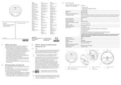
… orange ( … s off) flashes orange/green alternately ( … s off) flashes orange/green alternately ( … wireless connections can be set up at one wireless module GC 171. The LED (2) on the new wireless ceiling-mounted detector flashes green twice first, then lights up orange for one second and then flashes red four times. As soon as the LED (2) goes out after that, the connection can be set up.
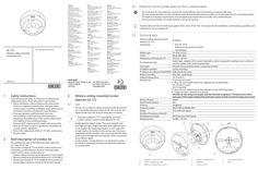
… orange ( … s off) flashes orange/green alternately ( … s off) flashes orange/green alternately ( … wireless connections can be set up at one wireless module GC 171. The LED (2) on the new wireless ceiling-mounted detector flashes green twice first, then lights up orange for one second and then flashes red four times. As soon as the LED (2) goes out after that, the connection can be set up.

Preventive fire protection in football stadiums – GEZE
… Orange Hotel - named after its location in the centre of Cape Town - was also renovated just in time for the World Cup. It is not only the elegant, consistent aesthetics of the GEZE door closer that come into play in the city's consummate boutique hotel. Automatic designer glass sliding doors also help to shape the inviting, transparent atmosphere at the 15 on Orange hotel. Sleek GEZE Slimdrive SL drive units, at just 70 mm high, move the fine-framed door leaves quietly and elegantly. GEZE door technology for the new World Cup airport A World Cup is inconceivable without a perfectly functioning aviation infrastructure: about a month before the beginning of the World Cup, the new King Shaka International Airport in the south of Durban commenced operation. Just like the stadiums and luxury hotels in the World Cup host country, the new airport used state-of-the-art and innovative door closing technology by GEZE to transport football fans and teams safely, quickly and comfortably between cities and continents. GEZE products in the New Green Point Stadium (Cape Town), the Oyster Box Hotel (Durban) and in King Shaka International Airport (Durban) Smoke and heat extraction systems (RWA) Electric RWA drives Overhead door closers with integrated closing sequence control for fire and smoke protection doors Electromagnetic hold-open function Integrated GEZE Boxer door closer Floor springs GEZE Slimdrive SL sliding door system Products used Boxer 1-leaf Boxer Integrated door closer for single leaf doors with a leaf width of up to 1400 mm Go to product Slimdrive Slimdrive SL NT Automatic linear sliding door system with low overall height and clear design line Go to product Related case studies and topics Health | Public buildings | References | Accessibility | Energy efficiency | Hygiene | safety Multi-functional door systems The Heidelberg Ethianum sets the highest standards in matters of convenience and safety. GEZE has equipped the multi-disciplinary new clinic building with innovative door systems and safety technology. Read more Topics | Accessibility Accessibility Accessibility allows everyone to live as equals, self-determinedly, and without external help. It ensures a better quality of life, greater comfort and increased safety for young and old. Read more Topics | Security | RWA | Fire protection Smoke and heat extraction Smoke and heat extraction (RWA) is part of preventive fire protection, and saves lives in the event of a fire. GEZE offers RWA solutions with intelligent drives for doors, windows and skylight domes. Read more