Search filter
10 results found

… jamb adjacent to the door. XX Establish the mounting position for the panic latch operating unit 10mm from the jamb. Place the template on the door and align the push bar/pad height and the rebate line with the jamb and drill the fixing holes required. Remove the template and fix the operating unit. XX For double doors establish the mounting position for the panic latch operating unit 10mm from the edge of the second door. Position the panic bolt operating unit on the last opening door 35mm from the panic latch operating body and fix. A Push Bar / Push Pad centre height: between 900mm & 1100mm B Push Bar length = B - 8mm Re-handing the panic / emergency exit latch … Standard latch keep P1601 Step C: Fitting the Keep XX For a single door fit the keep plate to the jamb. Note that only the keep face within the jamb rebate should be recessed to provide flush fitting. XX For double doors fit the box keep 300 to the adjacent (second opening) door. Note the position of the panic bolt unit for this application. … Fixing and installation XX Operate the panic latch and ensure that the latch bolt moves and returns freely, enters the keep fully and allows the door to be opened easily and closed securely. IQ Bar 100 Series Fixing the push bar Step D: Fitting the slave unit & push bar IQ Bar only XX Using the template position the slave unit on the door directly opposite the operating unit and 10mm from the jamb and fix. XX Measure the outside dimension (B) across the operating arms. Subtract 8mm and cut the plain end of the push bar to length. Drill a 10mm dia. hole in the plain end of the push bar on the centre line and 12mm from the end. XX Locate the push bar in the operating arms and ensure that the holes align with the arm clamp screws. Insert the end plugs into both ends of the push bar flush with the operating arms and fully tighten both screws. Step E: Testing the operation XX Test the unit to ensure that when the Push Bar/ Pad is operated the door opens immediately and swings freely. When closed the centre latch engages fully in the keep and holds the door securely shut. Step F: Fitting the name plate and the sign XX Remove backing paper and fit self adhesive body label into the recessed location on the body casting to cover top fixing screws. For push bar: Fit the self adhesive “Push Bar to Open” sign onto the door immediately above the push bar For push pad: Fit the self adhesive “Push Pad to Open” sign onto the door by the push pad. Centre latch keep double door (300) … Fixing and installation IQ Bar 102/ IQ Bar 102 A/ IQ Pad 102/ IQ Bar 104 DL These units can be fitted on a single door or in one of the following double door sets: àà Set IQ Bar 104 DL with IQ Bar 102 fitted on both leafs of non rebated double doors. àà Set IQ Bar 103 DL with IQ Bar 102 fitted on the last opening (inactive) leaf of double rebated doors together with IQ Bar 101 on the first opening (active) leaf. In this case a revised fitting position for this unit is however required, which is shown on the other unit’s installation instructions. In case of using an outside access device (OAD) fit the OAD first before continuing with the installation of the panic device. Step A: Fitting the main/operating unit XX Determine the height of the push bar/pad (A) between 900mm and 1100mm from floor level. Mark this position on the jamb adjacent to the door. XX Establish the mounting position for the panic bolt operating unit 10mm from the jamb. Place the template on the door and align the push bar/pad height and the rebate line with the jamb and drill the fixing holes required. Remove the template and temporarily fix the operating unit. XX For Non-Rebated double doors establish the mounting position for the panic bolt operating unit 10mm from the edge of its door leaf. Repeat the process on the second door. A Push Bar / Push Pad centre height: between 900mm & 1100mm B Push Bar length = B - 8mm Step B: Preparing the shoot tubes XX Refer to the diagram on page 10. Follow the correct procedure for your product: For IQ Bar 102 (standard shoot bolts) XX Accurately Measure the Bottom (short) length dimension (C1). XX When using the easy clean socket (G) or the alternative floor plate (not shown) subtract 8mm from length C1 and cut the plain end of the tube to this length. XX When using the surface mounted bottom keep 3405 (supplied separately) subtract 23mm from length C1 and cut the plain end of the tube to this length. XX Drive the bottom (short) shoot end plug No.P0601 into the cut end. XX The plug must be driven in fully against the tube end. XX Accurately Measure the Top (long) length dimension (C2). XX When using the Top trip plate P0401 (as supplied) subtract 54mm from length C2 and cut the plain end of the tube to this length. … Fixing and installation XX XX XX When Using the Surface mounted top keep 3405A (supplied separately) subtract 69mm from length C2 and cut the plain end of the tube to this length. Drive the top (long) shoot end plug No. P0501 into the cut end. The plug must be driven in fully against the tube end. For IQ Bar 102 A (adjustable shoot bolts) XX Accurately Measure the Bottom (short) length dimension (C1). XX When using the easy clean socket (G) or the alternative floor plate (not shown) subtract 66mm from length C1 and cut the plain end of the tube to this length. XX When using the surface mounted bottom keep 3405 (supplied separately) subtract 81mm from length C1 and cut the plain end of the tube to this length. XX Drive threaded shoot bush No. P0164 into the cut end. The Bush must be driven in fully against the tube end. XX Screw bottom (plain) shoot end No. P0162 into the shoot bush leaving a 4mm gap. XX Accurately Measure the Top (long) length dimension (C2). XX When using the Top trip plate P0401 (as supplied) subtract 61mm from length C2 and cut the plain end of the tube to this length. XX When Using the Surface mounted top keep 3405 (supplied separately) subtract 76mm from length C2 and cut the plain end of the tube to this length. XX Drive threaded shoot bush No. P0164 into the cut end. The Bush must be driven in fully against the tube end. XX Screw the top (grooved) shoot end No. P0159 into the shoot bush leaving a 4mm gap. Step C: Fitting the shoot tubes and guides XX Remove the panic bolt operating unit from the door and fit top & bottom shoot tube assemblies to the panic bolt unit spigots and retain with socket head screws positioned adjacent to the door face. XX Position shoot guides No. P0201 on the shoot tubes (for IQ 102 A use guide No. P0206 for the bottom tube). Refit panic bolt unit and fit guides to the door using the round head screws. Shoots must be vertical and panic bolt unit and guides must be in alignment. XX Keeping the operating arm fully depressed locate the top trip assembly No. P1201 on the top shoot end. Use a 3mm thick spacer between the end of the top shoot and the underside of the head frame to ensure that the shoot is fully withdrawn and secure the top trip guide assembly to the door. 10 IQ Bar 100 Series Adjustable bolt with GAP L C1 C2 D E F G H I J K L Bottom shoot tube length Top shoot tube length Top trip plate Tube Guides Socket head screws Easy clean floor socket No. P0301 Main/operating unit Slave unit Top Trip Guide Assembly Bottom Tube guide (P0201 Non-adjustable bolts / P0206 Adjustable bolts) 55mm (Adjustable Bolts & standard keep) 70mm (Adjustable Bolts & surface mounted keep) 44mm (None-adjustable Bolts & standard keep) 59mm (Non-adjustable Bolts & surface mounted keep) Fixing the push bar IQ Bar 100 Series Step D: Fitting the keeps XX The Top Trip Keep Plate P0401 should be fitted flush in the head frame and with its narrow edge level with the frame rebate. Use the short c´sk. head screws provided. XX Easy clean floor socket No. P0301 for solid floors should be fitted flush with the finished floor surface and with its edge level with the inside door face. Alternative floor plate No. P1301 for wooden floors must be fitted flush with the finished floor surface and with its narrow edge level with the door face. XX Operate the panic bolt and ensure that the top trip device holds both shoots in the fully withdrawn position when the door is open. XX Close the door and ensure that the top trip releases the shoots to engage fully in both top and bottom keeps and holds the door firmly closed in its rebate. Step E: Fitting the slave unit & push bar IQ Bar only XX Using the template position the slave unit on the door directly opposite the operating unit and 10mm from the jamb and fix. XX Measure the outside dimension (B) across the operating arms. Subtract 8mm and cut the plain end of the push bar to length. Drill a 10mm dia. hole in the plain end of the push bar on the centre line and 12mm from the end. XX Locate the push bar in the operating arms and ensure that the holes align with the arm clamp screws. Insert the end plugs into both ends of the push bar flush with the operating arms and fully tighten both screws. Fixing and installation Top Trip Keep Plate P0401 Surface mounted bottom bolt keep 3405 surface mounted top trip keep 3405A Step F: Testing the operation XX Test the unit to ensure that when the Push Bar/ Pad is operated the door opens immediately and swings freely. When closed the bolts engage fully in the keeps and holds the door securely shut. Step G: Fitting the name plate and the sign XX Remove backing paper and fit self adhesive body label into the recessed location on the body casting to cover top fixing screws. For push bar: Fit the self adhesive “Push Bar to Open” sign onto the door immediately above the push bar For push pad: Fit the self adhesive “Push Pad to Open” sign onto the door by the push pad. 11 Fixing and installation Outside Access Device 100 K 58 mm The outside access device provides a lockable entry facility for doors fitted with IQ 100 Series. The outside access device always allows immediate exit regardless of whether device is locked or unlocked. For double door installations with rebated meeting door styles, the outside access device must be fitted on the first opening (last closing) door leaf. XX XX XX XX XX 12 Working on the inside face of the door use the template to establish the fixing position for Panic Bolt or Panic latch as described in the appropriate instruction page. In addition using the template mark and drill the drive spindle hole 14mm dia. and two outside access device mounting holes 7mm through and counterbore 14mm dia. x 6mm deep. Trial fit the c‘sk. head mounting screws/ washers and measure the projection on the outside of the door. Adjust the depth of the counterbore to provide 19mm screw projection. If projection exceeds 19mm cut the screw to length. Locate the drive spindle into the square hole in the outside access device. Pass the spindle through the door and fix the body securely. Ensure that the body is square to the edge of the door and that the drive spindle is centred in the hole and that it rotates freely. Ensure that the drive spindle is fully engaged on the outside access device. Cut the spindle so that 13mm projects from the door face. A minimum of 10mm is required for correct operation. Engage the drive spindle with the square hole in the panic bolt/panic latch and install following the appropriate fitting procedure instruction page. Test the operation of the outside access device. To open the door hold the knob to prevent it turning. Insert the key and turn it anti-clockwise one complete revolution (the key can then be removed if required). Rotate the knob until a slight click is felt. Continue to turn the knob approximately ¼ turn to operate the panic bolt/panic latch. To disengage the outside access device hold the knob and turn the key clockwise one revolution and remove. Check for free and correct operation of the outside access device and the panic bolt/panic latch. 100 mm 18 mm 19 mm 13 mm Ø 14 mm XX 71 mm OAD 100 K with Knob (cylinder cannot be removed) 50 mm

… jamb rebate (you may need to cut or fold the template) align with the unit centre line and the jamb line and stick to the door with sticky tape. For rebated double doors align the correct line on the double door template (DT-0072) with the edge of the inactive leaf and the unit centre line. Mark the positions of the holes for the mounting plate. Follow the instructions on the relevant template and drill the required holes. Fix the mounting plate to the door. All … Fixing and installation PAD 202 V A IQ Bar 200 Series 22mm 22mm Step A: Preparing the device XX Hand the main unit by removing the packaging and gently rotate the arm in the required direction (see diagram Step I) until it clicks. The unit is now handed. If handed incorrectly by mistake refer to Step I. XX Remove the mounting plate from the bottom of the main operating unit (pull out). XX XX XX A Unit Centre Height: between 930mm & 1130mm B Oval Push Bar Length = B + 61mm Starting at the opening edge, place the template (DT-0071) on the door and slide into the jamb rebate (you may need to cut or fold the template) align with the unit centre line and the jamb line and stick to the door with sticky tape. For Non-Rebated double doors align the correct line on the template (DT-0071) with the edge of its door leaf. Repeat the process on the second door. Mark the positions of the holes for the mounting plate. Follow the instructions on the relevant template and drill the required holes. Fix the mounting plate to the door. Repeat the process on the second door. All … IQ Bar 200 Series PAD 203 H Fixing and installation Step B: Fitting the mounting plate XX Determine the centre height (A) of the unit between 930mm and 1130mm from floor level. Mark this position on the edge of the door frame on both sides of the inside of the door. Note: The centre of the Push Bar/Pad will fall approximately 30mm below this. XX XX XX Starting at the opening edge, place the template (DT-0071) on the door and slide into the jamb rebate (you may need to cut or fold the template) align with the unit centre line and the jamb line and stick to the door with sticky tape. Mark the positions of the holes for the mounting plate. Follow the instructions on the template and drill the required holes. Fix the mounting plate to the door. All … IQ Bar 200 Series A These units can be fitted on a single door or on rebated double doors together with a latch unit. In this case a revised fitting position is required, which is shown in the relevent section of these instructions relating to that device. Step A: Preparing the device XX Hand the main unit by removing the packaging and gently rotate the arm in the required direction (see diagram Step I) until it clicks. The unit is now handed. If handed incorrectly by mistake refer to Step I. XX Remove the mounting plate from the bottom of the main operating unit (pull out). Step B: Fitting the mounting plate XX Determine the centre height of the unit between 930mm and 1130mm from floor level. Mark this position on the edge of the door frame, both sides of the inside of the door. Note: The centre of the Push Bar will fall approximately 30mm below this. XX XX XX XX For rebated single doors: starting at the opening edge, place the template (DT-0071) on the door and slide into the jamb rebate (you may need to cut or fold the template), align with the unit centre line and the jamb line and stick to the door with sticky tape. For flush doors align the correct line on the template (DT-0072) with the frame edge and the unit centre line. Mark the positions of the holes for the mounting plate. Follow the instructions on the template and drill the required holes. Fix the mounting plate to the door. All six fixing holes must be used and screw heads must not project above plate. Hand the slave, same process as the main unit (Step A), but the opposite hand. Repeat steps above to fit the slave unit mounting plate to the hinge side of the door. Fix this mounting plate to the door also using all

Accessibility for Stuttgart public library
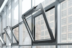
… jamb and the side wall of the bookshelves. First DIBt-certified and verified fire safety sliding door system GEZE developed innovative T30 fire protection glass sliding door systems equipped with Slimdrive SL drives for the Stuttgart public library, in collaboration with the door and gate specialist Hörmann. The collaboration is the first automatic fire safety sliding door system approved by the German Construction Technology Institute (DIBt). The fully glazed automatic sliding doors with fire resistance class T30 offer architects and planners a verified solution. GEZE products in the Stuttgart public library Slimdrive EMD F side-hung leaf drive GEZE TS 5000 series door closers Slimdrive EMD F-IS side-hung leaf drives Display programme switch with key switch Products used Guide rail 1-leaf TS 5000 Overhead door closer with guide rail for single leaf doors with a leaf width up to 1400 mm Go to product Slimdrive EMD Slimdrive EMD F-IS swing door drive system Electromechanical swing door system for double leaf fire and smoke protection doors with closing sequence control Go to product Programme switches DPS Display programme switch for setting the mode of operation for automatic doors Go to product Related case studies and topics Topics | Accessibility Accessibility Accessibility allows everyone to live as equals, self-determinedly, and without external help. It ensures a better quality of life, greater comfort and increased safety for young and old. Read more Public buildings | References | Accessibility | safety Door security in the judiciary centre The new Gelsenkirchen judiciary centre is characterised by its state-of-the-art design and sophisticated functionality. GEZE automatic doors contribute to convenience and safety in the building complex. Read more Historic buildings | References | Fire protection | Building refurbishment High-level technology in the Frauenkirche State-of-the-art window technology for the reconstructed Frauenkirche Dresden: GEZE has integrated tailor-made RWA systems into the historic building material. Read more

GEZE’s wireless solutions for hold-open systems in the Magdeburg cathedral
… jambs, statues, stucco areas, pillars etc.), is to be transformed into an exhibition and event space in future. The high number of visitors expected to use the space requires a possible hold-holding open of the doors. As the Carpenter Room is also planned as a separate fire protection section, the fire protection doors need to close automatically in case of alarm. Due to the extremely high ceilings, two additional ceiling-mounted detectors are required here. Cables would need to have been concealed in the joints, which would have meant significant additional expenses in the joint area as well as some chiselling and slitting work. Monument protection issues would have required complex and time-consuming legal and regulatory approvals. Wireless extensions Ideal for buildings with protected monument status: wireless extensions for hold-open systems. © Stefan Dauth / GEZE GmbH I am very familiar with Magdeburg Cathedral and its protected historical structure – after all, I conduct cathedral tours myself. Whilst the Schörghuber wooden fire protection doors are a good fit within the visual surroundings, technical elements such as door closers and smoke alarm systems present a challenge. GEZE’s discreet hold-open systems with wireless modules in conjunction with the wireless ceiling-mounted detectors are the ideal solution here, because no cable connections are required between the lintel-mounted and ceiling-mounted detectors. Wagner, Master Carpenter The wireless extension solution for GEZE’s hold-open systems had two other decisive pricing advantages: - Cost factor: eliminates the cost of laying cables - Time factor: reduces installation time Go to Wireless KIT GC 170 Hold-open systems in the organ loft provide quiet ease of access and fire protection A good example of the interplay between ease of use and modern fire protection measures can be seen in the access to the organ loft, which can be reached via two doors. One side serves as an entry, the other side as an exit – meaning there is no scramble when the church choir comes and goes. Because of the many comings and goings at certain times, it is crucial that the doors close quietly and can be kept open if necessary – after all, a solemn service should not be disturbed by slamming doors. At the same time, the hold-open systems must automatically close the fire doors in case of fire to prevent the spread of smoke and flames. It was particularly important to set up new fire protection closers for the organ loft, as only normal building doors were used here previously. There were no fire protection closers or other fire protection measures, only fire alarm systems. Two new wooden fire protection doors were manufactured by Tischlerei Wagner from Körbelitz, Germany. GEZE TS 5000 R guide rail door closers with an electrical hold-open device, continuously adjustable closing force and integrated back check ensure that the doors close quietly and are kept open if necessary. The smoke switch control unit integrated in the hold-open system makes sure that the doors close automatically in case of fire. Building stock Protected monument Historical doors of the protected monument require special measures. © Stefan Dauth / GEZE GmbH Fire doors with GEZE door closer GEZE door technology ensures ease of access and safety. © Stefan Dauth / GEZE GmbH Historic landmark and tourist attraction – Magdeburg Cathedral The imposing Magdeburg Cathedral is the emblem of the city. © Stefan Dauth / GEZE GmbH Officially the Cathedral of Saints Catherine and Maurice, Magdeburg Cathedral is considered the first cathedral in Germany to be completely designed in the Gothic style. The previous church on the site had nationwide significance as the burial place of the Holy Roman Emperor Otto the Great. The original cathedral was destroyed by fire in 1207. The complex construction of the Gothic cathedral began in 1209, and the dedication took place in 1363. The elaborate church construction took over 300 years. In 1520, the two imposing church towers were completed – the north tower and its outdoor platform can be visited as part of guided tours. The number of visitors shows just how important the historic building is today: in addition to churchgoers attending services in the present Protestant parish church, more than 100,000 tourists visit the impressive Gothic building every year. All GEZE products in Magdeburg Cathedral at a glance Hold-open systems with customised TS 5000 R and R-ISM door hold-open devices Wireless modules for connecting wireless components to GEZE GC 171 hold-open systems GC 172 wireless smoke detector for wireless connection to the GC 171 wireless module Products used Guide rail 2-leaf TS 5000 R-ISM Overhead door closer system with guide rail for double leaf doors with closing sequence control and smoke switch Go to product Wireless extensions GC 171 Radio module for wireless connection of wireless components to GEZE hold-open systems Go to product Related references and topics Historic buildings | References GEZE hold-open systems for optimum fire protection, now with wireless kit FA GC 170 Renovating buildings and changing the fire protection concept in listed buildings poses challenges, e.g. laying the cables for the fire protection solution. GEZE hold-open systems are the solution, now with our wireless kit FA GC 170. Read more Historic buildings | References | Fire protection | Building refurbishment High-level technology in the Frauenkirche State-of-the-art window technology for the reconstructed Frauenkirche Dresden: GEZE has integrated tailor-made RWA systems into the historic building material. Read more Topics | Building renovation Building renovation You can increase the comfort, the security and the energy efficiency of your existing properties through building renovation works. GEZE supports you in this with the right products. Read more
Window safety: secure power-operated windows
… jamb do not need further protection. Freely accessible windows where the lower edge of the leaf has a clearance of less than
Window safety: secure power-operated windows
… jamb do not need further protection. Freely accessible windows where the lower edge of the leaf has a clearance of less than

… jamb. Flush door: Centreline 26mm from thejamb. Double doors: Centreline 25mm from the last opening door edge. XX Choose the correct template (template 5). Stick the template to the door as explained on that template. Align the template with the touch bar mounting holes and the clearance hole. Mark the positions of the inner top and bottom outside access device mounting holes. XX Drill three 5mm dia fixing holes (Holes B) XX Drill 19mm dia. clearance (Hole A) hole through the door. XX Countersink all three holes (Holes B) 10mm dia. for timber doors (when using the dished washers, for steel doors countersink to suit) on the inside door face. XX Counterbore all three holes (Holes B) from the OUTSIDE of the door 8mm dia. x 22mm deep. (see diagram 1) XX Prepare three M4 c’sk. head screws. Measure the door thickness, subtract 8mm and cut to length (see diagram 1). XX Prepare the drive spindle. Measure the door IQ Bar 300 Series XX XX XX XX Fixing and installation thickness add12mm to this and cut the drive spindle to this length. Fit the drive spindle into the square hole (see diagram 1). Using the dished washers (for timber doors) and two screws. Secure the outside access device to the door using the top inner and bottom centre holes only. Ensure that drive spindle is positioned centrally in the clearance hole and that the body of the outside access device is square to the edge of the door. Install the touch bar panic device. Locate the drive spindle. Use the remaining screw in the top outer fixing hole to secure both the touch bar and the outside access device. Complete the installation of the touch bar as described in the appropriate fitting procedure sheet. Step B: Testing the device Once the panic device has been installed test for free and correct operation of both the outside access device & the panic device/s. … o‘clock position as required). XX Insert the lever set pin provided through the hole in the back plate situated below the square drive location. Engage the thread and thighten fully. Step B: Re-setting the outside access device’s lever if set the wrong way in error (see diagram 2) XX Operate the cylinder lock key in an anti-clockwise direction to lock the unit (disengage the mechanism).Remove the key. XX Remove the backplate assembly (4 screws).Taking care not to displace the drive spindle from the lever boss. XX Remove the lever set pin (if it has been fitted). XX Look inside the body. Locate the lever drive pin. Depress the spring loaded lever drive pin to disengage the lever from, the sprung disc. XX Gently rotate the lever towards the correct po- XX XX sition until the drive lever drive pin re-engages. Taking care not to rotate the sprung disc. Continue to move the lever against the spring pressure until it’s just past the horizontal position and the lever drive pin engages in the new position. Fit the lever set pin to retain the lever in its new position. Refit the backplate assembly (4 screws). Line up the setting marks on the drive spindle with those on the backplate assembly. Test the operation of the unit. Step C: Changing the cylinder lock To change the cylinder follow the steps below. XX Remove the backplate assembly (4 screws). Taking care not to displace the drive spindle from the lever boss. XX Remove the existing cylinder by removing the screw. Take care not to lose the tubular spacer. XX Place the new cylinder lock flat on the back plate locate the tubular spacer between the cylinder and fixing tag and secure with the screw. XX Refit the backplate assembly and test operation. Step D: Positioning the device XX Working on the inside face of the door establish the position for the Outside Access Device. Single door: Centreline 37mm from the jamb. Flush door: Centreline 26mm from the jamb. Double doors: Centreline 25mm from the last opening door edge. XX Choose the correct template (template 4). Stick 15 Fixing and installation the template to the door as explained on that template. Align the template with the touchbar mounting holes and the clearance hole. Mark the positions of the inner top and bottom outside access device mounting holes. For added security a 5th mounting screw (hole F on the template) is provided for an additional outside access device fixing. However this extra screw is only hidden from view when used in conjunction with two & three point panic units,but is visible on the inside face of the door on single point (latch) versions. XX XX XX XX XX XX XX XX XX XX XX XX Drill four / five (see above) 5mm dia fixing holes (Holes B, C, D, E & F). Drill the 19mm dia. clearance hole through the door (Hole A). Countersink the two inner holes (and the 5th hole if used) 10mm dia. for timber doors (when using the dished washers, for steel doors countersink to suit) on the inside door face (Holes C, D & F). Counterbore both top holes (see diagram A) from the OUTSIDE 8mm dia. x 22mm deep (Holes B & C). Prepare two (short) M4 c’sk. head screws for the top mounting holes (see diagram 3). Measure the door thickness, subtract 5mm and cut to length. Prepare two/three (long) M4 c’sk. head screws for the bottom mounting holes (see diagram 3). Take the door thickness dimension, add 12mm and cut to length. Prepare the drive spindle. Measure the door thickness add 12mm to this and cut the drive spindle to this length. Fit the drive spindle in to the square hole (see diagram 3). Ensure that the setting marks are in alignment. Using dished washers (for timber doors) and one short an one long c’sk. head screw. Secure the outside access device using the inner holes only. Ensure that the drive spindle is positioned centrally in the clearance hole and that the body of the outside access device is square to the edge of the door. Install the touch bar panic device. Locate the drive spindle. Use the two remaining screws, short (top) and long (bottom) in the outer fixing holes to secure both the touch bar and the outside access device. Complete the installation of the touchbar as described in the appropriate fitting procedure sheet. Step H: Testing the device Once the panic device has been installed test for free and correct operation of both the outside access device & the panic device/s. 16 IQ Bar 300 Series IQ Bar 300 Series
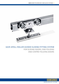
… jamb, every second leaf is fitted with a roller with pivot bearing and edge-fitting hanger. When choosing the track size and the roller, it should be noted that each roller has to take approximately the weight of two leaves. The use of double rollers is recommended. In the fold area the brackets for track mounting should be spaced at 350 mm (increased load-bearing). 20 GEZE DOOR TECHNOLOGY AND GLASS SYSTEMS Fig. 20-1 Manual sliding door systems GEZE APOLL ROLLER GUIDED SLIDING FITTING SYSTEM GEZE Apoll for folding doors – Size 0,1,2 0-10 1-10 2-10 0-35 1-35 0-42 1-42 0-1 1-1 0-33 1-33 0-11 1-11 0-1 1-1 0-44 1-44 0-65 1-65 0-52 1-52 2-52 0-53 1-53 1-54 Execution … z = number of leaves z z B = a a = leaf width, leaf hinged to jamb a1 = leaf width 2. leaf b = leaf thickness c = 1/2 hinges ø+1 d = b/2 n = 60 with size … h3 29 38 48,5 u 110 180 220 h4 43,5 55,5 72,5 v 20 20 30 h5 15 18 24,5 w 35 45 53 Manual sliding door systems 21 Manual sliding door systems GEZE APOLL ROLLER GUIDED SLIDING FITTING SYSTEM GEZE Apoll for folding doors – Size 0,1,2 0-32 1-32 2-32 0-14 1-14 2-14 0-1 1-1 0-20 1-20 2-20 0-41 1-41 2-41 The gaps between the individual leaves when closed up are not taken into account in calculating the leaf width. The leaf width should be adjusted according to choise of gap width. locking device by customers 0-51 1-51 2-51 a = leaf width, leaf hinged to jamb a1 = a + (c+d+n1) a1 = a2 = a3 ... an leaf width of following leaves a1 = a = a1-(c+d+n1) B+(c+d+n1) z+1 b = leaf thickness a = B-(a1 * z) c = 1/2 hinges ø+1 B = a+a1+a2+a3 ... an d = b/2 B = a + (a1 * z) z = number of leaves n1 = 18 with size … edge-fixing guide rollers d pivot point 160 mm pivot point 190 mm pivot point 160 mm pivot point 190 mm pivot point 90 mm 0-42 1-42 0-52 1-52 1-52 019019 s s s 012663 s 020522 s s s 012672 012672 s s = yes, s = no Ordering information GEZE Apoll folding door gear size ... number of leaves ... folding to right (left) , wall installation (or ceiling installation) ... block frame clearance height and width (H, B) 26 GEZE DOOR TECHNOLOGY AND GLASS SYSTEMS s Manual sliding door systems GEZE APOLL ROLLER GUIDED SLIDING FITTING SYSTEM GEZE Apoll for centre-folding doors – Size 0,1,2 Centre-folding, i. e. half inward and half outward. Centre-folding doors start with a half leaf hinged to the jamb. The rollers are fitted above the centre of the leaf. The first roller is normally positioned at the first full leaf. The track can be mounted with soffit- oder wall installation brackets. On the underside of each leaf, on the side towards which the leaf folds, a flush bolt is fitted. The floor guide should be arranged plumb underneath the roller carriage. The best leaf widths are between 600 mm and 900 mm. Fig. 27-1 Use