Search filter
12 results found
… color azul Identifica- XX Sujete la tarjeta maestra ción indidurante más de … segundos vidual / delante del lector Eliminar XX Retirar la tarjeta maestro llave XX Sujete la identificación a eliminar delante del lector àà El LED parpadea lentamente en color azul (0-5 seg.) àà El LED parpadea lentamente en color rojo (tras … seg.) XX Tarjeta maestra durante Todos Identificamás de 15 segundos delanciones / te del lector Eliminar la llave XX Retirar la tarjeta maestro àà àà àà àà àà àà àà LED parpadea lento en color azul àà El LED se ilumina permanentemente en color azul àà La salida en el controlador no se conecta (no se oye). Si no se detecta la identificación, el LED parpadeará de nuevo lentamente (45 seg.) Si, durante la "Memorización" o la "Eliminación individual", se sujeta la tarjeta maestra demasiado tiempo (más de 15 segundos) delante del lector, el LED parpadeará más rápidamente en color rojo y cambiará al modo "Eliminar todo". Para impedir el borrado de todas las identificaciones memorizadas, retire inmediatamente la tarjeta y espere hasta que el lector ya no parpadee y el LED azul se ilumine permanentemente (aprox. 45 seg.). àà El LED parpadea lentamente en color rojo àà El LED se ilumina permanentemente en color azul àà La salida en el controlador ya no se conecta. El LED parpadea lentamente en color azul (0-5 seg.) LED parpadea lentamente en color rojo (tras 5-10 seg.) LED parpadea rápidamente en color rojo (tras 10-15 seg.) El LED se apaga El LED permanece apagado durante … segundos El LED vuelve a iluminarse permanentemente en color azul En caso de pérdida de la llave o del transpondedor, deberá eliminarse toda la memoria por motivos de seguridad. Por último, memorice de nuevo todas las llaves aún disponibles. 13 ES | ESPAÑOL GEZE SecuLogic GCER 100 Datos técnicos 27,7 80 11,7 Medidas principales 60 Controlador Suministro de corriente AC: 8-12 V AC (máx. tensión en vacío factor 1,3) CC: Estabilizado: 9-12V CC, no estabilizado: máx. 20 V CC no cargado Entrada protegida ante la inversión de polaridad. Consumo de corriente máx. 150 mA Contacto de relé: Tipo de contacto Tensión de activación Corriente de conexión Tiempo de conexión Abridor/cierrapuertas, libre de potencial (ajustable mediante el herraje para puertas correderas tras la regleta de bornes) máx. 30 V CA / máx. 40 V CC máx.
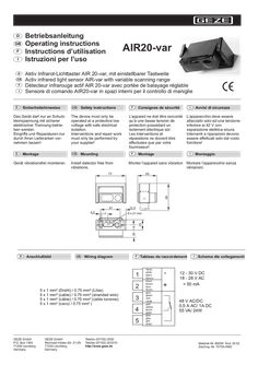
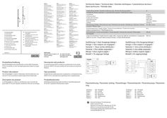
… color. CAUTION! Adjustment screw without stopper. Bitte beachten: Nicht weiter als Markierung 2,2 m drehen. Nicht in den Objektstrahl greifen. Tastobjekt mit niedrigstem Reimissionsvermögen (dunkelste Farbe) verwenden. Please observe: Do not pass the … m mark. Do not introduce your hands into the detection beam. Use workpieces with the lowest remission capacity (darkest color possible). 1. Installez le détecteur. 2. Alignez le détecteur . mécaniquement. 3. Connectez le détecteur (tension d’ utilisation, sorties). 4. Vis de réglage en position A: placer la flèche sur la plage de balayage mini (plaque de caractéristiques … m). ATTENTION! La vis de réglage ne dispose pas de butée. 5. Positionnez la pièce manipulée dans la zone de balayage désirée (LED désactivée en mode clareté; activée en mode obscurité). 6. Tournez la vis de réglage (position A) dans le sens contraire des aiguilles d’une montre jusqu’á ce que la LED change de couleur. ATTENTION! La vis de réglage ne dispose pas de butée. 1. Installare il sensore 2. Orientare meccanicamente il . sensore e fissarlo nell'archetto a rotazione con le due viti per lamiera a lente 3. Collegare il sensore elettricamente (alimentazione, uscite) 4. Vite di regolazione pos. A: regolare la freccia sul settore di rilevamento minimo (vedi targhetta del tipo 1,3 m, impostazione in ditta 1,3 m) ATTENZIONE! La vite di regolazione non ha arresto 5. Posizionare l'oggetto da rilevare sul settore di rilevamento desiderato (indicatore LED disattivato in modalità di chiaro, attivato in modalità di oscurità) 6. Girare la vite di regolazione (pos. A) in senso antiorario fino a che l'indicatore LED cambia lo stato. ATTENZIONE! La vite di regolazione non ha arresto. Note: Ne dépassez la marque des 2,2 m Ne placez pas la main dans la trajectoire du faisceau. Les pièces utilisées doivent être le plus sombres possible. Osservate: Non oltrepassare il segno di 2,2 m. Non mettere la mano nel raggio. Usare oggetti da rilevare dalla capacità di remissione più bassa possibile (il colore più scuro). N F E R ~1,5 m E = Sender / emitter / émetteur / trasmettitore LED ~2,5 m >500 mm ~1,2 m <2200 mm TO R = Empfänger / receiver / récepteur / destinatario TO = Tastobjekt / workpiece / pièce manipulée / oggetto da rilevare TG = Tastbereichsgrenze / scanning range limit / limite de balayage / limite del settore di rilevamento HG = Hintergrund / background / fond / sfondo Pos. A TG HG D Technische Daten Lichtsender Betriebsspannung F Caractér. techniques Light transmitter Operating voltage Emetteur de lumière tension d’alimentation Tastweiten-Einstellung Einstellbereich ca. 1300 - 2200 mm Lichtbündelquerschnitt ca. 60 mm bei Tastweite 1300 mm s/w-Differenz ca. 400 mm bei Tastweite 1300 mm Ansprechzeit ca. 50 ms Abfallzeit ca. 250 ms Schaltungsart dunkelschaltend infrared LED 12-30V DC 18-28V AC < 50 mA Power consumption Scanning area 200 - 2200 mm on white Kodak paper Scanning range setting Setting area approx. 1300 - 2200 mm Light bundle diam. approx. 60 mm with scanning range 1300 mm b/w difference approx. 400 mm with scanning range 1300 mm Response time approx. 50 ms Fail-delay approx. 250 ms Switching method dark background Signalausgang: Signal output: Sortie de signal : Relais 1x potentialfreier Wechselkontakt, aktiv bei Detektion max. Schaltspannung 48V AC/DC max. Schaltstrom 0,5A AC/1A DC max. Schaltleistung 55VA/24W Anschlußart: 5-pol. Steckschraubklemme, Kabel
… Color Incl. in delivery STRONG SYSTEM EN 1155 The GEZE range of hold-open magnets NOT approved for the German market floor, wall, surface-mounted IP 54 48 mm 48 V / 200 N (France) 24 V / 200 N (Italy/Spain) 230 VAC / 400 N (UK) light grey 0514 ID Nr. 159255 GEZE GmbH Reinhold-Vöster-Str. 21-29 71229 Leonberg Germany Tel.: +49 7152 203-0 Fax: +49 7152 203-310 E-Mail: vertrieb.services.de@geze.com www.geze.com counter plate 115956 BE WE GUNG M IT SYST E M DISCREET DESIGN. GEZE HOLD-OPEN MAGNETS... VERSATILE USE.
… color VERDE y el mecanismo de retención eléctrica recibe corriente. X Encajar la hoja de la puerta en el mecanismo de retención eléctrica. X Accionar la tecla de reseteo en el conmutador de humos. à El indicador de estado se ilumina en AMARILLO durante aprox. … s. à La puerta se cierra. à A continuación, el indicador de estado se iluminará de nuevo en color VERDE. prueba de recepción Una vez concluido el montaje del equipo, se ha de comprobar su funcionamiento correcto en el sitio de empleo y su debida instalación a través de una prueba de recepción. Para el examen de recepción por parte de personal técnico autorizado, tenga en cuenta el documento “Instrucciones para el montaje, la puesta en marcha, el manejo y el mantenimiento del sistema de retención GEZE FA GC”. Características técnicas Clase de protección Grado de protección Temperatura ambiente Cable de alimentación 230 V Tensión de alimentación: Tensión de funcionamiento: máx. consumo eléctrico II IP 20; sólo para recintos secos -5 °C a 50 °C NYM-O,
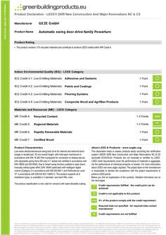
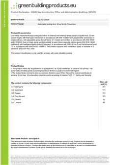
… color. About LEED & Products - www.usgbc.org This declaration helps to assess products easily according the certification system LEED® 2009 New Construction and Major Renovations NC & CS (excluded SCHOOLS). Products are not reviewed or certified by LEED. LEED credit requirements cover the performance of materials in aggregate, not the performance of individual products or brands. For more information about LEED visit www.usgbc.org/leed. The project team or the manufacturer is responsible to declare the compliance with the project requirements to achieve LEED points. Below you find an explanation of the symbols. Detailed information are on the next pages. The product classification is only valid for versions with water-dilutable coating. # # # Credit requirements fulfilled - the credit point can be achieved Credit is not applicable to this product 22% X% of the product comply with the credit requirement — Required data not specified - for required data contact manufacturer Credit requirements are not fulfilled Notice: This declaration is a product of HOINKA GmbH. This data sheet is published in the online database greenbuildingproducts.eu. The distribution by third parties is prohibited. This declaration is no official certificate in terms of LEED. The contents are based on manufacturer specifications. In spite of a diligent treatment of all information HOINKA GmbH cannot guarantee the actuality or correctness of the published data. The interpretation of the LEED criteria requirements can differ and depend on the project and the scope of application. In spite of a diligent treatment of all information HOINKA GmbH cannot guarantee the correctness of evaluation in terms of the LEED requirements. The user of this declaration, the consumer of the product and the consultant/planner, who is advising this product in any construction projects, is responsible by himself to proof all data published in this document and to verify the permissibility for the designated application. The content of this data sheet does not manifest any legal relationship. With the publication of a new edition, this declaration can no longer be considered to be valid. The latest version is available in the internet. HOINKA GmbH ▪ greenbuildingproducts.eu ▪ Lembergweg 7/1 ▪ 71067 Sindelfingen ▪ Tel. +49 7031 7659-441 ▪ Fax +49 7031 7659-443 ▪ www.greenbuildingproducts.eu ▪ contact@greenbuildingproducts.eu ▪ Geschäftsführer: Dipl.-Ing. Thomas Hoinka N/A If the location of 'Harvesting & Extraction' and 'Manufacturing' is within a radius of 500 miles of the project the subproduct contributes to the credit.
… color VERDE. Prueba de recepción Una vez concluido el montaje del equipo, se ha de comprobar su funcionamiento correcto en el sitio de empleo y su debida instalación a través de una prueba de recepción. En este sentido, tenga en cuenta el documento „Instrucciones para el montaje, la puesta en marcha, el manejo y el mantenimiento del sistema de retención GEZE FA GC“. Mantenimiento, conservación, reparación Se deberá realizar un mantenimiento periódico. En este sentido, tenga en cuenta el documento „Instrucciones para el montaje, la puesta en marcha, el manejo y el mantenimiento del sistema de retención GEZE FA GC“.
… color and structure. Reflecting and very dark objects are detected as well. Several sensors can be operated in a master and slave combination in order to be able to adapt the area protected to the prevailing conditions. By means of a six-pole screw terminal the master module is connected to the door control. The slave modules are connected to and supplied by the master module by means of flat cables. The master module and the slave modules are located in an aluminum profile together.
