Search filter
49 results found
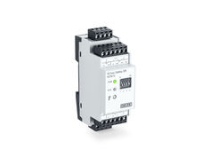
IQ box KNX
Interface module for connecting the Slimchain, Powerchain and E 250 NT window drives in the KNX building bus
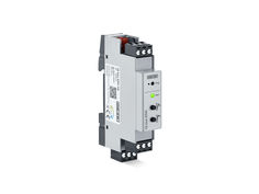
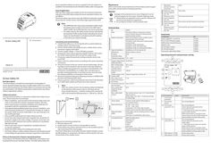
IQ box Safety
Safety module for protecting hazardous areas of power-operated windows
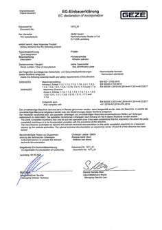
… byggas in, uppfyller bestämmelserna i detta direktiv. Tillverkaren åtager sig att på elektronisk väg skicka in de särskilda underlagen för den ofullständiga maskinen till nationella myndigheter vid förfrågan. De särskilda tekniska underlagen enligt bilaga VII del B har framtagits. Den ufullstendige maskinen må først tas i bruk når det er konstatert at maskinen, der den ufullstendige maskinen er montert, overholder bestemmelsene i retningslinjen. Produsenten forplikter seg til å formidle de spesielle dokumentene til ufullstendige maskiner til enkeltstatene elektronisk d ersom de krever det. De spesielle tekniske dokumentene er opprettet i henhold til denne retningslinjen, vedlegg VII, del B. Το ημιτελές μηχάνημα δεν πρέπει να τεθεί σε λειτουργία μέχρις ότου το τελικό μηχάνημα στο οποίο πρόκειται να ενσωματωθεί δηλωθεί ως σύμφωνο με τις διατάξεις της παρούσας οδηγίας. Ο κατασκευαστής αναλαμβάνει την υποχρέωση ηλεκτρονικής διαβίβασης του ειδικού φακέλου του ημιτελούς μηχανήματος στις εθνικές αρχές, μετά από δεόντως αιτιολογημένο αίτημα. Ο ειδικός τεχνικός φάκελος σύμφωνα με το Παράρτημα VII Μέρος B αυτής της οδηγίας έχει καταρτιστεί. Aðeins má taka óheildstæða vél í notkun ef komist hefur verið að niðurstöðu um að vélin, sem setja á óheildstæðu vélina í, uppfyllir ákvæði þessarar tilskipunar. Framleiðandinn skuldbindur sig til þess að senda yfirvöldum einstakra ríkja sérhæfð skjöl fyrir ófullgerða vél með rafrænum h ætti sé þess óskað. Sérstakar tækniupplýsingar samkvæmt B hluta VII. viðauka við þessa tilskipun hafa verið gefnar út. Person behörig att sammanställda de tekniska underlagen Fullmektig person til oppretting av teknisk dokumentasjon: Christoph Lieske / QMZ4 Adress se ovan Adresse se over Πληρεξούσιο άτομο για κατάρτιση του τεχνικού φακέλου Einstaklingur með heimild til að taka saman tækniskjöl Christoph Lieske / QMZ4 Διεύθυνση βλ. πάνω Heimilisfang má finna að ofan Giltig försäkran om överensstämmelse (EU): Gjeldende EU-konformitetserklæring: Dokumentnr 1071_01 Dokument Nr. 1071_01 Συνοδευτική δήλωση συμμόρφωσης ΕΕ: Samræmisyfirlýsing ESB sem einnig gildir: Αρ. εγγράφου 1071_01 Skjalanr. 1071_01 Leonberg,
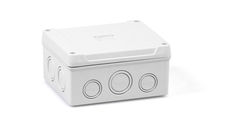
Junction box
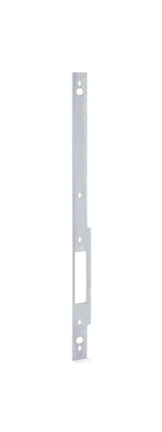
Spacer strike box
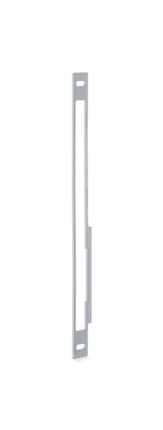
Support strike box
IQ box KNX
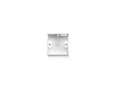
Surface mounted box
Area of application With the IQ box Safety and suitable sensors the maximum protection rating from the GEZE safety analysis for power-operated windows can be fulfilled. The IQ box Safety may only be used with GEZE IQ windowdrive window drives and non-contact sensors and safety edges approved by GEZE. Maintenance GEZE recommends annual maintenance of the window system to guarantee safety and permanent clamping protection. Disposal Damage to the environment can occur if disposal is not carried out properly. For this reason, heed the following notes: X Always follow the applicable country-specific disposal and environmental protection regulations. X Do not dispose of these with household waste. Note 193670-01 Translation of the original operating instructions for device version … / A0 IQ box Safety DR Brief description The IQ box Safety is a module for protecting the closing edges of power-operated windows by means of safety edges and/or non-contact sensors (pinch protection). The IQ box Safety is an accessory and can only be used together with GEZE IQ windowdrive window drives. One IQ box Safety is required per window. Safety instructions To ensure personal safety, it is important to follow these safety instructions. These instructions must be kept. à Before installation, read and observe the enclosed safety notes and notes on the protection of power-operated windows. Warranty claims require proper mounting, installation and maintenance in accordance with the manufacturer's specifications. à Only appropriately qualified people may carry out installation, commissioning and maintenance. If unauthorised changes are made to the system, GEZE cannot be made liable in any way whatsoever for any resulting damages. à Only use GEZE original parts for repair and service work. à Ensure that only a trained electrician completes the connection of the power supply to the mains voltage. The power connection and protective earth conductor test must be carried out in accordance DIN VDE 0100-600 à Observe the latest versions of guidelines, standards and country-specific regulations. à Protect the IQ box Safety from building dirt and water. à The IQ box Safety is a safety-related component and detailed specialist knowledge through product training is required to understand it. Notes on the protection of power-operated windows In accordance with Machinery Directive 2006/42/EC a risk analysis must be prepared for power-operated windows. The GEZE safety analysis for General information Connection and commissioning X Install IQ box Safety on a 35 mm top hat rail in a control cabinet or suitable surface-mounted casing. X Connect IQ box Safety and suitable sensors, window drives, activation/power supply as described. X Connect supply voltage -> Power LED lights up green. X Activate the sensor inputs required using DIP switches. (First, press the CLOSE window button (8) to activate the safety mode). X If necessary, adapt the parameter settings using the service case and ST220. X Teach-in the non-contact sensors according to the sensor operating instructions. X Check the function of the non-contact sensors/safety edges. All closing edges must be tested for safe operation under real conditions using a suitable testing element in accordance with EN 60335-2-103 (dimensions 25x100x300mm or smaller). Non-recorded areas or possible reaching behind the sensor field must be corrected using the setting possibilities or the position of the sensor. X Check the protection behaviour following activation in OPEN/CLOSE direction and following SHEV alarm. X Instruct customers, document protection (see note) in the risk analysis or GEZE safety analysis and hand over to the customer. Note: With non-contact sensors, the remaining residual risk depends on the distance of the sensor to the on-site limits (A) (e.g. frame, façade elements, ...) and the overlap of the risk area (B) GEZE recommends the following values: A < 300 mm, B > 500 mm. A 187677 One IQ box Safety is required per window. Up to … window drives and … locking drives can be used per window. Modes of operation SHEV and ventilation mode via SHEV control panel (polarity reversal mode) Ventilation mode with power supply (polarity reversal mode) Ventilation mode with IQ gear Ventilation mode with IQ box KNX Ventilation mode via control panel (F1200+) Type of installation Installation on 35 mm top hat rail Dimensions 90 mm x 60 mm x 35 mm IP rating IP 20 Protection rating III Ambient temperature -5°C…+70°C Supply voltage IQ box Safety and drives Max. residual ripple Max. current consumption drives Induced current intake Supply voltage of the sensors (24V) Max. total current load at 24V outputs for sensors Connection cross-section terminals Max. overall cable length for drives (LIN-BUS) Max. cable length sensors 18-30 V DC Sensor inputs … inputs, can be used for safety edges or non-contact sensors. GC 339+ (max. … pcs.) GC 342 (max. … pcs.) Combination with safety edges possible. Further sensors only after approval by GEZE Safety edges with terminating resistance of 4k5 to 22k Ohm max. … pcs. or combination with sensors. Sensor B B B Sensors EN Wiring diagram ID Note Approved sensors Approved safety edges B Compatible drives Measures for minimising residual risk: X Minimise distance (A). X Install a further sensor so that it is not possible to reach in. X IQ box Safety may only be used where the on-site conditions permit safe monitoring of the closing edges. The IQ box Safety does not provide protection against dangers caused by falling objects or components. No objects may be placed in the area of movement of the window leaves. Drives IQ box Safety DR Technical data Electrical data à The OPEN direction may not be protected in SHEV mode. If windows have to close in the event of an SHEV alarm (SHEV CLOSE), the CLOSE direction may not be protected. à For safety reasons, the safety mode must be activated by pressing the CLOSE window button (8) before the sensor inputs are deactivated or activated via the DIP switches or the drives are closed manually. Function (factory setting) power-operated windows can serve as a guide for the risk analysis. It is available in the download area for the IQ box Safety under www.geze.de. Software drives 20 U_ss [%] 10 A 100 mA Supply voltage IQ box Safety -6% Monitored direction of drive movement Behaviour when sensor triggered SI1 / SI3 Behaviour when sensor triggered SI2 / SI4 Behaviour when sensor released SI1 / SI3 Behaviour when sensor released SI2 / SI4 Close Drive stops Drive stops and reverses Drive carries out last movement command Drive waits for new movement command Accessories Designation Power supply NT … A-24 V HS NT … A-24 V HS power supply GEZE surface-mounted housing GEZE GC 339+ GC 342 (right module) GC 342 (left module) Connection cable IQ box Safety ID 151425 151424 152010 203858 167435 167432 193394 Operating elements and parameter setting … 4 … 5 … 8 … 11 121 132 10 … 1140 … 162 … 487 1980 … A … 3 … 6SI4 4L SI 24V … 7 … 13 … 5 4SI3 6A … 24V … 9 SYS … 4 SI … 1 … 10 … 8 … ON … 4 … max. … mm² 50 m … 2 … Non-contact sensors: max. 10 m - heed technical … data for sensors. Safety edges: max. 200 m - heed technical data … for safety edge. … 6 GEZE IQ windowdrives Slimchain 24 V Powerchain E 250 NT F1200 + Power lock The software status of the drives must be V3.2 or higher or V1.0 for F1200+. … 1 Pos. … Component4 … Connection activation … 2 Connection drives 3, … Connection sensor SI1 / SI3 … State … 8 4, … Connection sensor SI2 / SI4 … 7 … 8 … 9 812 … 3 … IQ box Safety … DR … 187672 PWR … 3 OUT S B DIP switches 1-4 ON DIP switches 1-4 OFF … 2 … 4 … 6 … 7 … 9 … 9 11 12 … 4 10 … 7 … 9 Explanation See wiring diagrams See wiring diagrams See wiring diagrams Sensor input pre-parameter set for non-contact sensors => deactivate sensor inputs not used by means of DIP switches. Before deactivation or activation of the sensor inputs, press the CLOSE window (8) button briefly to activate safety mode. See wiring diagrams Sensor input pre-parameter set for safety edges => deactivate sensor inputs not used by means of DIP switches. Before deactivation or activation of the sensor inputs, press the CLOSE window (8) button briefly to activate safety mode. Sensor input active Sensor input inactive … System LED … System LED … System LED on (red) 10 Power LED 10 Power LED on (green) off 10 Power LED 11 flashes (green) Service case and ST220 A B … S L … Sensor fault => Check sensor and sensor connection SI2 SI … 1 … 3 … 5 … 7 … 24V … 6 … 5 … 9 … 8 … RD BK WH … Internal error => Restart system (supply voltage OFF/ON), replace box. 24V TST A B … 4 S … + - + 24 V DC … SI1 GND SI L … 5 24V … SI2 SI … 4 … 6 … 8 N … 7 … 4 51 62 … 7 84 95 … 7 … 9 … 3 … 3 … 5 … 4 … 6 … 8 … 7 … 9 … 2 … PK … 24V … TST A PK … 3 … 5 … 4 … 6 … 8 … 7 … 9 … SI1 GND SI B … S … 1 TST … 5 24V L … SI2 … 3 … 5 … 7 … 9 GND SI GC 342 … Note: SI … 9 S … SHEV … control … panel GY … red black white … 6 BN 24V BN BU GN GY PK RD brown blue green grey pink red GC 339+ Note: X X GND SI GC 339+ RD BK … WH … PK … BU … 6 … BK … BU … RD … 5 Connection of sensors GC 342 or GC 339+ With mode of operation IQ box KNX, IQ gear, F1200+ Window GN … 4 Safety edge BU … 3 Note: X Connect safety edges to sensor inputs SI2 / SI4. X Note the permissible terminating resistors of the safety edges (see technical data). Heed the instructions for the safety edge. X The safety edges to be connected must be sized, mounted and put into operation independently, in accordance with the local circumstances and requirements of the Machinery Directive. RD … 2 … Connection window drives and activation … 1 … Connection safety edges TST GC 342 Sensors GC 342 and GC 339+ require a permanent 24 V supply. Therefore an additional 24 V power supply (e.g. power supply NT … A-24 V HS) is required in polarity reversal mode (SHEV control panel / power supply). X Connect sensors and 24 V power supply to sensor inputs SI1 / SI3. X Heed the instructions for the sensors. X X … Relay test has failed, failed initialisation process => Restart system (supply voltage OFF/ON), replace box. Sensor OK and sensor triggered; all sensor inputs deactivated. Ready for operation, power supply OK Communication to the drive OK Power supply not OK => Check power supply and connection to IQ box Safety. Power supply OK Communication to the drive not OK => Check connection of the drives to IQ box Safety. => Check software version of the drives on the type plate. SW version … or higher is required. Connection of the service case (e.g. using IQ box Safety connection cable) Connect output A,B,S,L of the service case to (1). For parameter setting see user manual ID 153523 - Parameter setting with service terminal ST220 and service case. 24V GY SI1 GND SI … BN TST … BU 24V … PK System LED IQ box Safety is in safety mode. … 24 V DC + - BK … System LED … 230 V AC 24 V power supply Connect sensor to sensor inputs SI1 / SI3. Heed the instructions for the sensors. BU … 1 230 V AC L1 N RD System LED … 5 … 7 … Connection of sensors GC 342 or GC 339+ With operating mode polarity reversal mode (SHEV control panel / power supply) GN … on (green) flashes slowly (green) 1s on/ 1s off flashes quickly (green) 100 ms on/ 100 ms off flashes slowly (red) 1s on/ 1s off flashes quickly (red) 100 ms on/ 100 ms off flashes (yellow) IQ box Safety DR IQ windowdrive window drive Optional branching box and further slave drives (with Syncro) orlocking drives IQ box KNX in flush-mounting or top hat rail casing IQ gear and power supply Power supply with polarity reversal F1200+ activation via control panel SHEV control panel; install line monitoring at the last window; S line for distinction alarm/ventilation BU System LED … 2 … PK … Button pressure activates safety mode for … seconds. Sensors can only be deactivated or activated via DIP switch in safety mode and the window drives can be closed e.g. in the event of sensor fault by pressing the CLOSE window push button again in dead man's operation. Sensor OK No sensor triggered Push button for overriding sensor signals is pressed, window closes. RD Window CLOSE push button PK 8
IQ box Safety