Search filter
82 results found
TS 5000 L-E-ISM VPK
… bar, integrated closing sequence control and electric hold-open device
TS 5000 L-ISM VPK
Overhead door closer system with guide rail, for opposite hinge side, for double leaf doors with anti-panic function and closing sequence control

… Bar 100 Series Panic & Emergency Exit Hardware 143799-02 GB Installation instructions IQ Bar 100 Series Table of Contents … IQ Bar 101/ IQ Pad 101 … IQ Bar 102/ IQ Bar 102 A/ IQ Pad 102/ IQ Bar 104 DL … 20 IQ Bar 100 Series … Product description The GEZE IQ Panic & Emergency Exit hardware devices are designed to give instant escape, when required, by means of either a push bar or push pad on single or double doors, and can be operated from the outside of the door by an outside access device. When the outside access device is locked the door can still be released from the inside. … Product overview IQ Bar 100 Series … Technical parts list Top shoot end plug Push Bar Bottom shoot end plug … Push Pad 1. Top trip plate 2. Top shoot end plug 3. Top trip guide 4. Top shoot tube 5. Tube guide 6. Tube screws 7. Push bar main unit 8. Oval cross bar 9. Slave unit 10. Tube end plug 11. Push pad actuator 12. Push pad main unit 13. Latch keep 14. Bottom shoot tube 15. Adjustable bottom tube guide 16 Bottom shoot end plug 17 Alternative floor plate 18 Body label IQ Bar 100 Series Hardware range Single Door Sets … Point Panic Bolts IQ BAR 102 Push Bar … Point Panic Bolt with shoot bolts IQ BAR 102 A Push Bar … Point Panic Bolt with adjustable shoot bolts PAD 101 PAD 102 IQ BAR 101 Push Bar … Point Panic Latch BAR 102 A BAR 101 BAR 102 … Point Panic Bolt with shoot bolts IQ Bar 103 DL Push Bar … Point Double Door Set for rebated double doors BAR 102 BAR 102 BAR 102 Double Door Sets BAR 101 … Product overview IQ Bar 104 DL Push Bar … Fixing and installation IQ Bar 100 Series … Introduction àà These exit devices are suitable for right or left hand opening doors of up to 2440mm (8’) high x 1220mm (4’) wide. àà The door must weigh no more than 200kg and be mounted in a good quality well made frame. àà The door/doors should be checked to ensure correct hanging and freedom from binding. àà It is not recommended that the exit device is fitted to hollow core doors. àà The exit devices are not intended for use on double action (double swing) doors. àà Ensure that no weather strips or fixings on the door or door frame stop the device from working properly. àà If the door is to be fitted with a device which allows you to open it from outside, read the instructions provided with that device. àà All measurements are in millimetres. àà For installation of double door sets refer to the instuctions of the relevant single door units. àà IQ Bar 103 V DL àà IQ Bar 104 V DL … = IQ Bar 101 = IQ Bar 102 + IQ Bar 102 + IQ Bar 102 IQ Bar 100 Series … Fixing and installation IQ Bar 101/ IQ Pad 101 These units can be fitted on a single door. IQ Bar 101 can also be fitted on the first opening (active) leaf of the IQ Bar 103 DL double doors set. In this case a revised fitting position for the unit is however required as shown on these installation instructions. In case of using an outside access device (OAD) fit the OAD first before continuing with the installation of the panic device. Step A: Re-handing the panic latch (if required) Supplied as standard the push bar/pad panic latch is assembled to suit right hand opening doors. To reverse the assembly to suit left hand opening doors proceed as follows. XX 1. Remove the panic latch backplate followed by the drive casting and actuating pressing. XX 2. The latch bolt/blanking casting assembly is reversible in the body by compressing between forefinger and thumb and replacing in the required position. XX 3. Reverse the position of the actuating pressing on the drive casting. Refit in the latch body ensuring that the drive casting pivot is correctly located and that the drive casting spigot is fully engaged with the latch bolt pressing. XX … . Refit the backplate and test for correct operation. Step B: Fitting the main/operating unit XX Determine the height of the push bar/pad (A) between 900mm and 1100mm from floor level. Mark this position on the jamb adjacent to the door. XX Establish the mounting position for the panic latch operating unit 10mm from the jamb. Place the template on the door and align the push bar/pad height and the rebate line with the jamb and drill the fixing holes required. Remove the template and fix the operating unit. XX For double doors establish the mounting position for the panic latch operating unit 10mm from the edge of the second door. Position the panic bolt operating unit on the last opening door 35mm from the panic latch operating body and fix. A Push Bar / Push Pad centre height: between 900mm & 1100mm B Push Bar length = B - 8mm Re-handing the panic / emergency exit latch … Fixing and installation XX Operate the panic latch and ensure that the latch bolt moves and returns freely, enters the keep fully and allows the door to be opened easily and closed securely. IQ Bar 100 Series Fixing the push bar Step D: Fitting the slave unit & push bar IQ Bar only XX Using the template position the slave unit on the door directly opposite the operating unit and 10mm from the jamb and fix. XX Measure the outside dimension (B) across the operating arms. Subtract 8mm and cut the plain end of the push bar to length. Drill a 10mm dia. hole in the plain end of the push bar on the centre line and 12mm from the end. XX Locate the push bar in the operating arms and ensure that the holes align with the arm clamp screws. Insert the end plugs into both ends of the push bar flush with the operating arms and fully tighten both screws. Step E: Testing the operation XX Test the unit to ensure that when the Push Bar/ Pad is operated the door opens immediately and swings freely. When closed the centre latch engages fully in the keep and holds the door securely shut. Step F: Fitting the name plate and the sign XX Remove backing paper and fit self adhesive body label into the recessed location on the body casting to cover top fixing screws. For push bar: Fit the self adhesive “Push Bar to Open” sign onto the door immediately above the push bar For push pad: Fit the self adhesive “Push Pad to Open” sign onto the door by the push pad. Centre latch keep double door (300) … IQ Bar 100 Series … Fixing and installation IQ Bar 102/ IQ Bar 102 A/ IQ Pad 102/ IQ Bar 104 DL These units can be fitted on a single door or in one of the following double door sets: àà Set IQ Bar 104 DL with IQ Bar 102 fitted on both leafs of non rebated double doors. àà Set IQ Bar 103 DL with IQ Bar 102 fitted on the last opening (inactive) leaf of double rebated doors together with IQ Bar 101 on the first opening (active) leaf. In this case a revised fitting position for this unit is however required, which is shown on the other unit’s installation instructions. In case of using an outside access device (OAD) fit the OAD first before continuing with the installation of the panic device. Step A: Fitting the main/operating unit XX Determine the height of the push bar/pad (A) between 900mm and 1100mm from floor level. Mark this position on the jamb adjacent to the door. XX Establish the mounting position for the panic bolt operating unit 10mm from the jamb. Place the template on the door and align the push bar/pad height and the rebate line with the jamb and drill the fixing holes required. Remove the template and temporarily fix the operating unit. XX For Non-Rebated double doors establish the mounting position for the panic bolt operating unit 10mm from the edge of its door leaf. Repeat the process on the second door. A Push Bar / Push Pad centre height: between 900mm & 1100mm B Push Bar length = B - 8mm Step B: Preparing the shoot tubes XX Refer to the diagram on page 10. Follow the correct procedure for your product: For IQ Bar 102 (standard shoot bolts) XX Accurately Measure the Bottom (short) length dimension (C1). XX When using the easy clean socket (G) or the alternative floor plate (not shown) subtract 8mm from length C1 and cut the plain end of the tube to this length. XX When using the surface mounted bottom keep 3405 (supplied separately) subtract 23mm from length C1 and cut the plain end of the tube to this length. XX Drive the bottom (short) shoot end plug No.P0601 into the cut end. XX The plug must be driven in fully against the tube end. XX Accurately Measure the Top (long) length dimension (C2). XX When using the Top trip plate P0401 (as supplied) subtract 54mm from length C2 and cut the plain end of the tube to this length. … Fixing and installation XX XX XX When Using the Surface mounted top keep 3405A (supplied separately) subtract 69mm from length C2 and cut the plain end of the tube to this length. Drive the top (long) shoot end plug No. P0501 into the cut end. The plug must be driven in fully against the tube end. For IQ Bar 102 A (adjustable shoot bolts) XX Accurately Measure the Bottom (short) length dimension (C1). XX When using the easy clean socket (G) or the alternative floor plate (not shown) subtract 66mm from length C1 and cut the plain end of the tube to this length. XX When using the surface mounted bottom keep 3405 (supplied separately) subtract 81mm from length C1 and cut the plain end of the tube to this length. XX Drive threaded shoot bush No. P0164 into the cut end. The Bush must be driven in fully against the tube end. XX Screw bottom (plain) shoot end No. P0162 into the shoot bush leaving a 4mm gap. XX Accurately Measure the Top (long) length dimension (C2). XX When using the Top trip plate P0401 (as supplied) subtract 61mm from length C2 and cut the plain end of the tube to this length. XX When Using the Surface mounted top keep 3405 (supplied separately) subtract 76mm from length C2 and cut the plain end of the tube to this length. XX Drive threaded shoot bush No. P0164 into the cut end. The Bush must be driven in fully against the tube end. XX Screw the top (grooved) shoot end No. P0159 into the shoot bush leaving a 4mm gap. Step C: Fitting the shoot tubes and guides XX Remove the panic bolt operating unit from the door and fit top & bottom shoot tube assemblies to the panic bolt unit spigots and retain with socket head screws positioned adjacent to the door face. XX Position shoot guides No. P0201 on the shoot tubes (for IQ 102 A use guide No. P0206 for the bottom tube). Refit panic bolt unit and fit guides to the door using the round head screws. Shoots must be vertical and panic bolt unit and guides must be in alignment. XX Keeping the operating arm fully depressed locate the top trip assembly No. P1201 on the top shoot end. Use a 3mm thick spacer between the end of the top shoot and the underside of the head frame to ensure that the shoot is fully withdrawn and secure the top trip guide assembly to the door. 10 IQ Bar 100 Series Adjustable bolt with GAP L C1 C2 D E F G H I J K L Bottom shoot tube length Top shoot tube length Top trip plate Tube Guides Socket head screws Easy clean floor socket No. P0301 Main/operating unit Slave unit Top Trip Guide Assembly Bottom Tube guide (P0201 Non-adjustable bolts / P0206 Adjustable bolts) 55mm (Adjustable Bolts & standard keep) 70mm (Adjustable Bolts & surface mounted keep) 44mm (None-adjustable Bolts & standard keep) 59mm (Non-adjustable Bolts & surface mounted keep) Fixing the push bar IQ Bar 100 Series Step D: Fitting the keeps XX The Top Trip Keep Plate P0401 should be fitted flush in the head frame and with its narrow edge level with the frame rebate. Use the short c´sk. head screws provided. XX Easy clean floor socket No. P0301 for solid floors should be fitted flush with the finished floor surface and with its edge level with the inside door face. Alternative floor plate No. P1301 for wooden floors must be fitted flush with the finished floor surface and with its narrow edge level with the door face. XX Operate the panic bolt and ensure that the top trip device holds both shoots in the fully withdrawn position when the door is open. XX Close the door and ensure that the top trip releases the shoots to engage fully in both top and bottom keeps and holds the door firmly closed in its rebate. Step E: Fitting the slave unit & push bar IQ Bar only XX Using the template position the slave unit on the door directly opposite the operating unit and 10mm from the jamb and fix. XX Measure the outside dimension (B) across the operating arms. Subtract 8mm and cut the plain end of the push bar to length. Drill a 10mm dia. hole in the plain end of the push bar on the centre line and 12mm from the end. XX Locate the push bar in the operating arms and ensure that the holes align with the arm clamp screws. Insert the end plugs into both ends of the push bar flush with the operating arms and fully tighten both screws. Fixing and installation Top Trip Keep Plate P0401 Surface mounted bottom bolt keep 3405 surface mounted top trip keep 3405A Step F: Testing the operation XX Test the unit to ensure that when the Push Bar/ Pad is operated the door opens immediately and swings freely. When closed the bolts engage fully in the keeps and holds the door securely shut. Step G: Fitting the name plate and the sign XX Remove backing paper and fit self adhesive body label into the recessed location on the body casting to cover top fixing screws. For push bar: Fit the self adhesive “Push Bar to Open” sign onto the door immediately above the push bar For push pad: Fit the self adhesive “Push Pad to Open” sign onto the door by the push pad. 11 Fixing and installation Outside Access Device 100 K 58 mm The outside access device provides a lockable entry facility for doors fitted with IQ 100 Series. The outside access device always allows immediate exit regardless of whether device is locked or unlocked. For double door installations with rebated meeting door styles, the outside access device must be fitted on the first opening (last closing) door leaf. XX XX XX XX XX 12 Working on the inside face of the door use the template to establish the fixing position for Panic Bolt or Panic latch as described in the appropriate instruction page. In addition using the template mark and drill the drive spindle hole 14mm dia. and two outside access device mounting holes 7mm through and counterbore 14mm dia. x 6mm deep. Trial fit the c‘sk. head mounting screws/ washers and measure the projection on the outside of the door. Adjust the depth of the counterbore to provide 19mm screw projection. If projection exceeds 19mm cut the screw to length. Locate the drive spindle into the square hole in the outside access device. Pass the spindle through the door and fix the body securely. Ensure that the body is square to the edge of the door and that the drive spindle is centred in the hole and that it rotates freely. Ensure that the drive spindle is fully engaged on the outside access device. Cut the spindle so that 13mm projects from the door face. A minimum of 10mm is required for correct operation. Engage the drive spindle with the square hole in the panic bolt/panic latch and install following the appropriate fitting procedure instruction page. Test the operation of the outside access device. To open the door hold the knob to prevent it turning. Insert the key and turn it anti-clockwise one complete revolution (the key can then be removed if required). Rotate the knob until a slight click is felt. Continue to turn the knob approximately ¼ turn to operate the panic bolt/panic latch. To disengage the outside access device hold the knob and turn the key clockwise one revolution and remove. Check for free and correct operation of the outside access device and the panic bolt/panic latch. 100 mm 18 mm 19 mm 13 mm Ø 14 mm XX 71 mm OAD 100 K with Knob (cylinder cannot be removed) 50 mm … IQ Bar 100 Series Dim. A. Push Bar Height IQ Bar 100 Series … mm XX Step B: Cylinder preparation This 100 K EC master keying outside access device is normally supplied complete with cylinder lock but for specific applications will accept most 40mm Euro profile cylinders if required. To suit master keying situations the outside access device can be supplied with pre-formed aperture to suit Euro profile cylinder fitting. The cylinder selected should be drilled and tapped M5 as shown. 19,5 mm Step C: Cylinderfitting Place the cylinder into the shaped body aperture and fix securely through the backplate with the c’sk head M5 screw supplied. Dim. A. Push Bar Height Drill and Tap M5 12 mm 13 Fixing and installation … .3 OAD 100 L EC with Lever and Euro Cylinder IQ Bar 100 Series Diagram … cylinder bracket screws as shown in diagram 3. Withdraw the cylinder bracket from the unit. XX Change / install the cylinder. Secure cylinder to bracket with the M5 x 20 cylinder screw provided. XX Replace the bracket / cylinder assembly. Re-secure with the cylinder bracket screws. 14 B / L LH position To suit IQ Bar/Pad 102 regardless of door handing and IQ Bar/Pad 101 used on left hand doors L RH position To suit IQ Bar/Pad 101 used on right hand doors Diagram … IQ Bar 100 Series Fixing and installation Step B: Device installation Establish unit position Working on the inside face of the door. Use the template to establish the fixing position of the panic / emergency exit device. Follow the instructions on the template. Determine height 900mm to 1100mm from floor. Align template correctly with the edge of frame (for single door) or the edge of 2nd opening door (for double doors). For existing installations where access device is to be retrofitted remove the exit device and align template with the existing exit device fixing holes. Door preparation XX Pilot the exit device fixing holes. Drill ø16mm spindle hole through the door. XX For timber doors: drill through … (standard projection) Panic / Emergency exit devices should be used in situations where there is restricted width for escape, or where the doors to be fitted with the Panic / Emergency exit devices are not able to open beyond 90°. àà Where an exit device is to be fitted to a glazed door, it is essential that the glazing is tempered or laminated glass. àà Different fixings are available for fitting Panic / Emergency exit devices to metal doors, etc. Timber fixings are supplied as standard. Note: Exit devices suffixed ‘SD’ (101 SD) include steel door fixings as standard. àà None of our Panic / Emergency exit devices are intended for use on double action (double swing) doors. àà The fixing instructions should be carefully followed during installation. These instructions should be passed on by the installer to the user. àà The horizontal bar (EN1125 devices) / operating element (EN179 devices) should normally be installed at a height of between 900 mm and 1100 mm from the finished floor level, when the door is in the secured position. Where it is known that the majority of the occupants of the premises will be young children, consideration should be given to reducing the height of the bar / operating element accordingly. àà The horizontal bar should be installed so as to provide the maximum effective length (EN1125 devices) àà When installing (EN179) lever operated Emergency exit devices, particularly on doors with raised or recessed surfaces, consideration should be given to minimizing any potential safety risks, such as the trapping of fingers or clothing. àà The bolt heads / latches and keepers should be fitted to provide secure engagement. Care should be taken to ensure that no projection of the bolt heads / latches, when in the withdrawn position, can prevent the door swinging freely. àà Where exit devices are to be fitted to double doorsets with rebated meeting stiles and self closing devices, a door coordinator device in accordance with EN 1158 should be fitted to ensure the correct closing sequence of the doors. This recommendation is particularly important with regard to fire/smoke resisting door assemblies. àà No additional devices for securing the door in the closed position should be fitted. This does not preclude the installation of self closing devices. àà If a door closing device is to be used to return the door to the closed position, care should be taken not to impair the use of the doorway by the young, elderly and infirm. àà Any keepers or protection plates provided should be fitted in order to ensure compliance with EN1125 / EN179. àà EN1125 Panic exit devices: the provided sign which reads; “Push bar to open” should be affixed on the inside face of the door immediately above the horizontal bar. àà EN179 Emergency exit devices: the provided sign which reads; “Push Pad to open” should be affixed on the inside face of the door immediately above the Push Pad operating element. 17 … - to fit the outside access device 100 K EC / 100 L EC onto the door NOTE:HOLES & RECESS ONLY REQUIRED FOR OUTSIDE ACCESS DEVICE. 1000mm ± 100mm FROM FLOOR EDGE OF DOOR (SINGLE DOOR) / EDGE OF 2ND OPENING DOOR (DOUBLE DOORS) 10mm 10mm LISTED ACCESSORIES Only the accessories listed below can be used with this product range. The use of any other accessory may invalidate the relevant products EN1125 / EN179 CE certification. PRODUCT No. DESCRIPTION COMPATIBILITY 3404 OUTSIDE ACCESS DEVICES Knob operated Outside Access Device Knob operated Outside Access Device with Euro cylinder Knob operated Outside Access Device with Oval aperture (cylinder not supplied) KEEPS Standard Latch Keep – Steel Door (Similar to P1601) 3405 Surface mounted Bottom bolt Keep 3405A Surface mounted Top Trip Keep 300 ED150 Double door latch keep (As Supplied with: IQ Bar 103 DL) Single & Double Door Latch Keep –Surface Mounted. P0401 Standard Top Trip Plate P1301 Standard Floor Plate bolt keep. P1601 Standard Latch Keep – Timber Door (Similar to 3404) 100K 100 K EC 100 L EC (Replaces 3404 / P1601 on single doors. Replaces 300 on double doors.) Use with all GEZE IQ Bar 100 series range for use with IQ Bar 101, IQ Pad 101 on steel doors IQ Pad 102, IQ Bar 102, IQ Bar 104 DL, IQ Bar 103 DL IQ Pad 102, IQ Bar 102, IQ Bar 104 DL, IQ Bar 103 DL IQ Bar 101, IQ Pad 101 IQ Bar 101, IQ Pad 101 IQ Pad 102, IQ Bar 102, IQ Bar 103 DL, IQ Bar 104 DL IQ Pad 102, IQ Bar 102, IQ Bar 103 DL, IQ Bar 104 DL IQ Bar 101, IQ Pad 101 Unless other wise stated compatibility is assumed with all the various suffixed variations (e.g. ‘A’, ‘SD’, ‘MS’) of the basic product. CE MARKING All devices are intended for use on single / double outward opening route escape doors, fire / none-fire rated dependant on device (see below). Where fire rated; devices are certified for use on the following door assemblies for the stated times: 60 minutes on Timber door assemblies (doorsets to EN 1634-1 Codes: TT, ITT and ITC). 240 minutes on Steel door assemblies (doorsets to EN 1634-1 Codes: IMM, and MM). Minimum resistance for all devices: a maximum pulling force of 1000N was achieved against the fixings under the abuse test. Below is the CE marking information for the entire range. Applicable products are clearly listed below their relevant markings. 1121 EN 1125: 2008 PANIC EXIT DEVICES … Projection. Field of Door application: Category A (Single & Double) Field of Door application: Category A (Single & Double) Suitable for use on fire / smoke doors. Suitable for use on fire / smoke doors. Applicable to Products: IQ Bar 102, IQ Bar 102A, IQ Bar 101, IQ Bar 104 DL, IQ Bar 103 DL Applicable to Products: IQ Pad 102, IQ Pad 101 GEZE GmbH, Reinhold-Vöster-Str. 21-29, D-71229 Leonberg 21 Notes: 22 Notes: 23 Germany GEZE GmbH Niederlassung Süd-West Tel. +49 (0) 7152 203 594 E-Mail: leonberg.de@geze.com GEZE GmbH Niederlassung Süd-Ost Tel. +49 (0) 7152 203 6440 E-Mail: muenchen.de@geze.com GEZE GmbH Niederlassung Ost Tel. +49 (0) 7152 203 6840 E-Mail: berlin.de@geze.com GEZE GmbH Niederlassung Mitte/Luxemburg Tel. +49 (0) 7152 203 6888 E-Mail: frankfurt.de@geze.com GEZE GmbH Niederlassung West Tel. +49 (0) 7152 203 6770 E-Mail: duesseldorf.de@geze.com GEZE GmbH Niederlassung Nord Tel. +49 (0) 7152 203 6600 E-Mail: hamburg.de@geze.com GEZE Service GmbH Tel. +49 (0) 1802 923392 E-Mail: service-info.de@geze.com Austria GEZE Austria E-Mail: austria.at@geze.com www.geze.at Hungary GEZE Hungary Kft. E-Mail: office-hungary@geze.com www.geze.hu Scandinavia – Sweden GEZE Scandinavia AB E-Mail: sverige.se@geze.com www.geze.se Baltic States – Lithuania / Latvia / Estonia E-Mail: baltic-states@geze.com Iberia GEZE Iberia S.R.L. E-Mail: info.es@geze.com www.geze.es Scandinavia – Norway GEZE Scandinavia AB avd. Norge E-Mail: norge.se@geze.com www.geze.no Benelux GEZE Benelux B.V. E-Mail: benelux.nl@geze.com www.geze.be www.geze.nl India GEZE India Private Ltd. E-Mail: office-india@geze.com www.geze.in Scandinavia – Denmark GEZE Danmark E-Mail: danmark.se@geze.com www.geze.dk Bulgaria GEZE Bulgaria - Trade E-Mail: office-bulgaria@geze.com www.geze.bg Italy GEZE Italia S.r.l E-Mail: italia.it@geze.com www.geze.it Singapore GEZE (Asia Pacific) Pte, Ltd. E-Mail: gezesea@geze.com.sg www.geze.com China GEZE Industries (Tianjin) Co., Ltd. E-Mail: chinasales@geze.com.cn www.geze.com.cn GEZE Engineering Roma S.r.l E-Mail: italia.it@geze.com www.geze.it South Africa GEZE South Africa (Pty) Ltd. E-Mail: info@gezesa.co.za www.geze.co.za GEZE Industries (Tianjin) Co., Ltd. Branch Office Shanghai E-Mail: chinasales@geze.com.cn www.geze.com.cn GEZE Industries (Tianjin) Co., Ltd. Branch Office Guangzhou E-Mail: chinasales@geze.com.cn www.geze.com.cn GEZE Industries (Tianjin) Co., Ltd. Branch Office Beijing E-Mail: chinasales@geze.com.cn www.geze.com.cn France GEZE France S.A.R.L. E-Mail: france.fr@geze.com www.geze.fr Korea GEZE Korea Ltd. E-Mail: info.kr@geze.com www.geze.com Poland GEZE Polska Sp.z o.o. E-Mail: geze.pl@geze.com www.geze.pl Romania GEZE Romania S.R.L. E-Mail: office-romania@geze.com www.geze.ro Russia OOO GEZE RUS E-Mail: office-russia@geze.com www.geze.ru Switzerland GEZE Schweiz AG E-Mail: schweiz.ch@geze.com www.geze.ch Turkey GEZE Kapı ve Pencere Sistemleri E-Mail: office-turkey@geze.com www.geze.com Ukraine LLC GEZE Ukraine E-Mail: office-ukraine@geze.com www.geze.ua United Arab Emirates/GCC GEZE Middle East E-Mail: gezeme@geze.com www.geze.ae United Kingdom GEZE UK Ltd. E-Mail: info.uk@geze.com www.geze.com GEZE GmbH Reinhold-Vöster-Straße 21–29 71229 Leonberg Germany Tel.: 0049 7152 203

… Bar 200 Series Panic & Emergency Exit Hardware 143800-01 GB Installation instructions IQ Bar 200 Series Table of Contents … IQ Bar 201/ IQ Pad 201 … IQ Bar 202 V A / IQ Bar 203 V A / IQ Pad 202 V A / IQ Bar 204 V DL … IQ Bar 203 H / IQ Pad 203 H … 12 IQ Bar 202 V … 26 IQ Bar 200 Series … Product description The GEZE IQ Panic & Emergency Exit hardware devices are designed to give instant escape, when required, by means of either a push bar or push pad on single or double doors, and can be operated from the outside of the door by an outside access device. When the outside access device is locked the door can still be released from the inside. … Product overview IQ Bar 200 Series … Push Bar … Push Pad 1. Oval push bar 2. Top shoot tube 3. Bottom shoot tube 4. Tube guide 5. Push bar main unit 6. Slave unit 7. Push pad main unit 8. Shoot bush 9. Top trip guide 10. Top shoot end plug 11. Bottom shoot end plug 12. Adjustable bottom tube guide 13. Alternative floor plate 14. Vertical pullman catch cover 15. Vertical pullman latch 16 Horizontal pullman latch 17 Horizontal pullman catch cover IQ Bar 200 Series Hardware range Horizontal Pullman Catches IQ BAR 202 V A Push Bar … Point Panic Bolt adjustable shoot bolts IQ BAR 203 H Push Bar … Point Panic Bolt horizontal pullman catches IQ BAR 202 V Push Bar … Point Panic Bolt vertical pullman catches BAR 203 V A IQ BAR 201 Push Bar … Point Panic Latch Vertical Pullman Catches BAR 202 V BAR 201 BAR 202 V A Adjustable Bolts BAR 203 H Single Door Sets Centre Latch PAD 201 PAD 203 H IQ BAR 203 V A Push Bar … Point Emergency Exit Bolt horizontal pullman catches IQ Bar 203 V DL Push Bar … Point Double Door Set for rebated double doors BAR 202 V A BAR 202 V A BAR 202 V Double Door Sets BAR 201 … Product overview IQ Bar 204 V DL Push Bar … Fixing and installation IQ Bar 200 Series … Introduction àà This exit devices are suitable for right or left hand opening doors of up to 2440mm (8’) high x 1220mm (4’) wide. àà The door must weigh no more than 200kg and be mounted in a good quality well made frame. àà The door/doors should be checked to ensure correct hanging and freedom from binding. àà It is not recommended that the exit device is fitted to hollow core doors. àà The exit devices are not intended for use on double action (double swing) doors. àà Ensure that no weather strips or fixings on the door or door frame stop the device from working properly. àà If the door is to be fitted with a device which allows you to open it from outside, read the instructions provided with that device. àà All measurements are in millimetres. àà For installation of double door sets refer to the instuctions of the relevant single door units. àà IQ Bar 203 V DL àà IQ Bar 204 V DL àà IQ Pad 203 V DL … = IQ Bar 201 = IQ Bar 202 V A = IQ Pad 201 + IQ Bar 202 V + IQ Bar 202 V A + IQ Pad 202 V A A These units can be fitted on a single door or on the first opening (active) leaf of one of the following rebated double doors sets. àà Set IQ Bar 203 V DL together with IQ Bar 202 V fitted on the last opening (inactive) leaf. àà Set IQ Pad 203 V DL with IQ Pad 202 V A fitted on the last opening (inactive) leaf. If the unit is to be fitted on double rebated doors a revised fitting position for the unit is however required as shown in these installation instructions. BAR 201 IQ Bar 201/ IQ Pad 201 A … Fixing and installation PAD 201 IQ Bar 200 Series 22mm 22mm 22mm Step A: Preparing the device XX Hand the main unit by removing the packaging and gently rotate the arm in the required direction (see diagram Step G) until it clicks. The unit is now handed. If handed incorrectly by mistake refer to Step G. XX Remove the mounting plate from the bottom of the main operating unit (pull out). Step B: Fitting the mounting plate XX Determine the centre height (A) of the unit between 930mm and 1130mm from floor level. Mark this position on the edge of the door frame on both sides of the inside of the door. For double doors also mark this position on the edge of the inactive leaf. Note: The centre of the Push Bar/Pad will fall approximately 30mm below this. XX XX XX Starting at the opening edge, place the template (DT-0071) on the door and slide into the jamb rebate (you may need to cut or fold the template) align with the unit centre line and the jamb line and stick to the door with sticky tape. For rebated double doors align the correct line on the double door template (DT-0072) with the edge of the inactive leaf and the unit centre line. Mark the positions of the holes for the mounting plate. Follow the instructions on the relevant template and drill the required holes. Fix the mounting plate to the door. All … fixing holes must be used and screw heads must not project above plate. IQ Bar 201 only XX Hand the slave, same process as the main unit (Step A), but the opposite hand. XX Repeat the steps above to fit the slave unit mounting plate to the hinge side of the door. Fix this mounting plate to the door also using all … fixing screws. In case of using an outside access device (lever) pause the installation of the exit device and fit the lever before continuing with the installation. Refer to chapter “Lever 200 L - (OAD) C B A B C D E Unit Centre Height: between 930mm & 1130mm Oval Push Bar Length = B + 61mm Centre Latch Keep No. 0140 Distance from the edge of the last opening leaf to Tube Centre Line = minimum 50mm Rebated Double Door Keep No. 0144 B 22mm 10mm D 22mm E … CSK Screws provided. Step D: Fitting the keep Single door XX With the door closed, position the included centre latch keep No. 0140 (C) centred about the latch with the flat face against the door face. XX Mark the positions of the fixing holes. XX Fix in place using the countersunk screws provided. Rebated Double doors XX For rebated double doors use the included keep No. 0144 (E). Position on last opening leaf with ‘lip’ against edge of door and centre about the latch (see diagram). XX Mark the positions of the fixing holes. XX Fix in place using the screws provided. XX Fit as shown and adjust with the packers provided until the correct engagement is achieved. Step E: Fitting the slave unit & oval cross bar IQ Bar 201 only XX Temporarily fit the slave unit onto the mounting plate. XX Measure accurately the arm gap (B) (see diagram) add 61mm to this dimension and cut oval cross bar to this length. XX Remove slave unit from its mounting plate insert one end of oval cross bar into the main unit arm and the other into the slave unit arm. XX Refit the slave unit onto the mounting plate and secure using three of M5x8 CSK Screws provided. XX Secure the cross bar with the two of M4x6 set screws one in each arm. DO NOT OVER TIGHTEN Step F: Testing the operation & fitting the sign. XX Test the unit to ensure that when the Push Bar/ Pad is operated the door opens immediately and swings freely. When closed the centre latch engages fully in the keep and holds the door securely shut. XX Fit the green self adhesive ‘Push Bar to Open’ / ‘Push Pad to Open’ sign onto the door positioned immediately above the Push Bar/Pad. … IQ Bar 200 Series Step G: Re-Handing the unit (If required) If either unit is handed the wrong way in error, please follow these instructions. XX Turn the unit upside down & pull out the mounting plate to remove it (if required) XX Slide a small flat bladed screwdriver into the smaller bit of the large aperture along the inside face of the steel chassis inserting it between the chassis and the handing cam (see the diagram). XX Gently lever the cam forward until it disengages from the arm spindle. XX Rotate the arm to re-hand the unit the required way (ensure the cam is fully engaged). 22mm A BAR 203 V A A These units can be fitted on a single door or in one of the following double door sets: àà Set IQ Bar 204 V DL with IQ Bar 202 V A fitted on both leafs of non rebated double doors. àà Set IQ Pad 203 V DL with IQ Pad 202 V A fitted on the last opening (inactive) leaf of double rebated doors together with IQ Bar 201 on the first opening (active) leaf. In this case a revised fitting position for this unit is however required, which is shown in the relevent section of these instructions relating to that device. BAR 202 V A IQ Bar 202 V A / IQ Bar 203 V A / IQ Pad 202 V A / IQ Bar 204 V DL A … Fixing and installation PAD 202 V A IQ Bar 200 Series 22mm 22mm Step A: Preparing the device XX Hand the main unit by removing the packaging and gently rotate the arm in the required direction (see diagram Step I) until it clicks. The unit is now handed. If handed incorrectly by mistake refer to Step I. XX Remove the mounting plate from the bottom of the main operating unit (pull out). XX XX XX A Unit Centre Height: between 930mm & 1130mm B Oval Push Bar Length = B + 61mm Starting at the opening edge, place the template (DT-0071) on the door and slide into the jamb rebate (you may need to cut or fold the template) align with the unit centre line and the jamb line and stick to the door with sticky tape. For Non-Rebated double doors align the correct line on the template (DT-0071) with the edge of its door leaf. Repeat the process on the second door. Mark the positions of the holes for the mounting plate. Follow the instructions on the relevant template and drill the required holes. Fix the mounting plate to the door. Repeat the process on the second door. All … fixing holes must be used and screw heads must not project above plate. IQ Bar 202 V A & 203 V A only XX Hand the slave, same process as the main unit (Step A), but the opposite hand. XX Repeat the steps above to fit the slave unit mounting plate to the hinge side of the door. Fix this mounting plate to the door also using all … fixing screws. BAR 202 V A XX B BAR 202 V A Step B: Fitting the mounting plate XX Determine the centre height (A) of the unit between 930mm and 1130mm from floor level. Mark this position on the edge of the door frame on both sides of the inside of the door. For double doors also mark this position on the edge of the inactive leaf. Note: The centre of the Push Bar/Pad will fall approximately 30mm below this. B 22mm 22mm 22mm 22mm … M5x8 CSK Screws provided. XX Locate the adjustable bottom tube guide the correct distance from the floor / frame (see diagram) and secure using the round headed screws provided. XX Locate the bottom middle guide equidistant on the tube (see diagram) and secure using the round headed screws provided. Ensuring the tube is vertical and the guides are in alignment. 10 IQ Bar 200 Series 3mm D 8mm GAP. K K C D E F G H I J K Adjustable Bottom Tube Guide Top Trip Guide Centre Latch Keep (IQ Bar 203 V A only) Bottom Shoot Tube Length Top Shoot Tube Length Top Trip Plate Easy Clean Socket Centre Latch (IQ Bar 203 V A only) Tube Guides IQ Bar 200 Series Step E: Fitting the top trip & top guide. XX Keeping the operating arm fully depressed. Locate the top trip guide device on the top shoot end plug. Use a 3mm thick spacer between the end of the top shoot and the underside of the frame / face of keep, to ensure that the shoot is fully withdrawn. Secure top trip guide to door using the round headed screws provided. XX Locate the top middle guide equidistant on the tube (see diagram) and secure using the round headed screws provided. Ensuring the tube is vertical and the guide and top trip are in alignment. XX Operate the exit device to ensure the top trip guide holds both shoots in the fully withdrawn position when the door is open. Step F: Fitting the keeps. XX Fit the top trip plate (H) morticed flush into the frame, with its narrow edge level with the door rebate (see diagram). Fix with the short (3/4” Long) countersunk screws provided. XX For solid floors fit the easy clean socket. Fit flush with the finished floor surface with its edge level with the inside door face. For wooden floors fit the alternative floor plate. Fit flush with the finished floor surface with the narrow edge level with the inside door face. Fixing and installation Step H: Testing the operation & fitting the sign. Test the unit to ensure that when the Push Bar/ Pad is operated the door opens immediately and swings freely. When the door is open the shoots are held fully withdrawn and when closed the shoots (and centre latch if present) engage fully in their keepers and hold the door securely closed. XX Fit the green self adhesive ‘Push Bar to Open’ / ‘Push Pad to Open’ sign onto the door positioned immediately above the Push Bar/Pad. Step I: Re-Handing the unit (If required) If either unit is handed the wrong way in error, please follow these instructions. XX Turn the unit upside down & pull out the mounting plate to remove it (if required) XX Slide a small flat bladed screwdriver into the smaller bit of the large aperture along the inside face of the steel chassis inserting it between the chassis and the handing cam (see the diagram). XX Gently lever the cam forward until it disengages from the arm spindle. XX Rotate the arm to re-hand the unit the required way (ensure the cam is fully engaged). XX IQ Bar 203 V A only XX With the door closed, position the centre latch keep (E) centred about the latch (J) with the flat face against the door face. Mark the positions of the fixing holes. Fix in place using the countersunk screws provided.“ XX Step G: Fitting the slave unit & oval cross bar. IQ Bar 202 V A & 203 V A only XX Temporarily fit the slave unit onto the mounting plate. XX Measure accurately the Arm Gap B (see diagram) add 61mm to this dimension and cut oval cross bar to this length. XX Remove slave unit from its mounting plate insert one end of oval cross bar into the main unit arm and the other into the slave unit arm. XX Refit the slave unit onto the mounting plate and secure using three of M5x8 CSK Screws provided. XX Secure the cross bar with the two of M4x6 set screws one in each arm. DO NOT OVER TIGHTEN 11 A Step A: Preparing the device XX Hand the main unit by removing the packaging and gently rotate the arm in the required direction (see diagram Step I) until it clicks. The unit is now handed. If handed incorrectly by mistake refer to Step I. XX Remove the mounting plate from the bottom of the main operating unit (pull out). BAR 203 H IQ Bar 203 H / IQ Pad 203 H A … IQ Bar 200 Series PAD 203 H Fixing and installation Step B: Fitting the mounting plate XX Determine the centre height (A) of the unit between 930mm and 1130mm from floor level. Mark this position on the edge of the door frame on both sides of the inside of the door. Note: The centre of the Push Bar/Pad will fall approximately 30mm below this. XX XX XX Starting at the opening edge, place the template (DT-0071) on the door and slide into the jamb rebate (you may need to cut or fold the template) align with the unit centre line and the jamb line and stick to the door with sticky tape. Mark the positions of the holes for the mounting plate. Follow the instructions on the template and drill the required holes. Fix the mounting plate to the door. All … fixing holes must be used and screw heads must not project above plate. IQ Bar 203 H only XX Hand the slave, same process as the main unit (Step A), but the opposite hand. XX Repeat the steps above to fit the slave unit mounting plate to the hinge side of the door. Fix this mounting plate to the door also using all six fixing screws. In case of using an outside access device (lever) pause the installation of the exit device and fit the lever before continuing with the installation. Refer to chapter Lever 200 L - (OAD) Step C: Positioning and fitting the pullman catches. XX Determine the height of the catches on the door. XX Place the template (DT-0074) on the door. Line up the appropriate lines. Mark the corresponding holes. XX Follow the instructions on the relevant template and drill the required holes. XX Remove the covers from the pullman units (2 cover screws). XX Fit each pullman catch using all three CSK screws provided. Note: to access two of the three screw holes; move the slide plate mechanism. Screw heads must be fully in the countersunk holes and not stand proud. 12 A Unit Centre Height: A = between 930mm & 1130mm B Oval Push Bar Length = B + 61mm C Centre Latch Keep D Top/Bottom Guide E Top/Bottom Keep F Bottom Shoot Tube Length = F + 7mm G Top Shoot Tube Length = G + 7mm H Pullman catch I Centre Latch IQ Bar 200 Series Step D: Preparing the shoot tubes. Rotate the mounting plate cam to the correct position (see template) and fit the main unit onto the mounting plate. XX Temporarily secure using one of the supplied M5 x … CSK screws. XX Measure accurately length (F), add 7mm and cut the plain end of the shorter tube to this length. XX Measure accurately length (G), add 7mm and cut the plain end of the longer tube to this length. XX Using the installation drift tube to prevent screw thread damage, drive the threaded shoot end plug into cut ends of both tubes. Plug must be driven in fully against the tube end. XX Re-fit the pullman catches (two cover screws, each) Step E: Fitting the shoot tubes, tube guides & main operating unit. XX Remove the main operating unit from the door. XX Screw the previously prepared shoot tubes (section C) fully into the pullman catches. XX Slide the tube guides onto the tubes (one on each tube) XX Ensure the mounting plate cam is in the correct position (see template). XX Place the main operating unit onto the mounting plate allowing the tubes to drift to one side. XX Operate the main operating unit mechanism to retract the shoot spigots. Guide the shoot tubes into position and slowly release the mechanism whilst guiding the spigots into the end of the tubes. XX Unscrew the tubes from the pullman catches until they almost contact the shoulder on the shoot spigots. Rotate the tubes back until the holes are facing the door. XX Pull the unit away from the door and secure the tubes using the M5x10 cap head screws provided. XX Fit unit back on the mounting plate and secure using three M5x8 CSK Screws. XX Locate the guides equidistant on the tubes (see diagram) and secure using the round headed screws provided. Ensuring the tubes are vertical and the guides are in alignment. Fixing and installation Step G: Fitting the slave unit & oval cross bar IQ Bar 203 H only XX Temporarily fit the slave unit onto the mounting plate. XX Measure accurately the arm gap (B) (see diagram) add 61mm to this dimension and cut Oval cross bar to this length. XX Remove slave unit from its mounting plate insert one end of oval cross bar into the main unit arm and the other into the slave unit arm. XX Refit the slave unit onto the mounting plate and secure using three of M5x8 CSK Screws provided XX Secure the cross bar with the two of M4x6 set screws one in each arm. DO NOT OVER TIGHTEN Step H: Testing the operation & fitting the sign. XX Test the unit to ensure that when the Push Bar/ Pad is operated the door opens immediately and swings freely. When the door is closed the pullman catches and centre latch engage fully in their keeps and hold the door securely closed. XX Fit the green self adhesive ‘Push Bar to Open’ / ‘Push Pad to Open’ sign onto the door positioned immediately above the Push Bar/Pad. Step I: Re-Handing the unit (If required) If either unit is handed the wrong way in error, please follow these instructions. XX Turn the unit upside down & pull out the mounting plate to remove it (if required) XX Slide a small flat bladed screwdriver into the smaller bit of the large aperture along the inside face of the steel chassis inserting it between the chassis and the handing cam (see the diagram). XX Gently lever the cam forward until it disengages from the arm spindle. XX Rotate the arm to re-hand the unit the required way (ensure the cam is fully engaged). Step F: Fitting the keeps. XX Position the included top/bottom keeps centred about the catch with the square face of the keep against the door (see diagram) and mark the holes. Fix in place using the countersunk screws provided. XX With the door closed, position the centre latch keep around the centre latch with the flat face against the door face. Mark the positions of the fixing holes. Fix in place using the countersunk screws provided. 13 Fixing and installation IQ Bar 202 V BAR 202 V … IQ Bar 200 Series A These units can be fitted on a single door or on rebated double doors together with a latch unit. In this case a revised fitting position is required, which is shown in the relevent section of these instructions relating to that device. Step A: Preparing the device XX Hand the main unit by removing the packaging and gently rotate the arm in the required direction (see diagram Step I) until it clicks. The unit is now handed. If handed incorrectly by mistake refer to Step I. XX Remove the mounting plate from the bottom of the main operating unit (pull out). Step B: Fitting the mounting plate XX Determine the centre height of the unit between 930mm and 1130mm from floor level. Mark this position on the edge of the door frame, both sides of the inside of the door. Note: The centre of the Push Bar will fall approximately 30mm below this. XX XX XX XX For rebated single doors: starting at the opening edge, place the template (DT-0071) on the door and slide into the jamb rebate (you may need to cut or fold the template), align with the unit centre line and the jamb line and stick to the door with sticky tape. For flush doors align the correct line on the template (DT-0072) with the frame edge and the unit centre line. Mark the positions of the holes for the mounting plate. Follow the instructions on the template and drill the required holes. Fix the mounting plate to the door. All six fixing holes must be used and screw heads must not project above plate. Hand the slave, same process as the main unit (Step A), but the opposite hand. Repeat steps above to fit the slave unit mounting plate to the hinge side of the door. Fix this mounting plate to the door also using all … CSK screws. XX Measure accurately the bottom length (G), Subtract 111mm and cut the plain end of the 14 A B C D F E G H Unit Centre Height: A = between 930mm & 1130mm Oval Push Bar Length = B + 61mm Pullman catch Top/Bottom Guide Pullman Flush Door Keep No. 406A Top/Bottom Keep Bottom Shoot Tube Length = G - 111mm Top Shoot Tube Length = H - 111mm IQ Bar 200 Series XX XX shorter tube to this length. Measure accurately the top length H, Subtract 111mm and cut the plain end of the longer tube to this length. (For flush doors subtract 101mm) Using the installation drift tube to prevent screw thread damage, drive the threaded shoot end plug into cut ends of both tubes. Plug must be driven in fully against the tube end. Step D: Positioning and fitting the pullman catches. XX To establish the mounting position for the top and bottom pullman catchess first determine which type of keep/striker is required for the installation. Standard door/floor keep (included) or Pullman flush door keep No. 406A (F) (see diagram). XX Place the template (DT-0073) on the door. Line up the appropriate lines. Mark the corresponding holes. XX Follow the instructions on the relevant template and drill the required holes. XX Remove the covers from the pullman catchess (two cover screws) XX Fit the pullman catches, using CSK screws provided. Re-fit the covers. Step E: Fitting the shoot tubes, guides & main unit. XX Remove the main unit from the door. XX Screw the previously prepared shoot tubes (section B) fully into the pullman catches. XX Slide the guides onto the tubes (one on each tube) XX Ensure the mounting plate cam is in the correct position (see template). XX Place the main unit onto the mounting plate allowing the tubes to drift to one side. XX Operate the main unit mechanism to retract the shoot spigots. Guide the shoot tubes into position and slowly release the mechanism whilst guiding the spigots into the end of the tubes. XX Unscrew the tubes from the pullman catchess until they almost contact the shoulder on the shoot spigots. Rotate the tubes back until the holes are facing the door. XX Pull the unit away from the door and fix the tubes using the M5x10 cap head screws provided. XX Fit unit back on the mounting plate and secure using three M5x8 CSK Screws. XX Locate the guides equidistant on the tubes (see diagram) and secure using the round headed screws provided. Ensuring the tubes are vertical and the guides are in alignment. Fixing and installation screws provided. For flush door use keep No. 406A. Fit as shown and adjust with packers until the correct engagement is achieved. Step G: Fitting the slave unit & oval cross bar. XX Temporarily fit the slave unit to the mounting plate. XX Measure accurately the arm gap (B) (see diagram) add 61mm to this dimension and cut oval cross bar to this length. XX Remove slave unit from its mounting plate insert one end of oval cross bar into the main unit arm and the other into the slave unit arm. XX Refit the slave unit to the mounting plate and secure using three M5x8 CSK Screws provided. XX Secure the cross bar with the two of M4x6 set screws one in each arm. DO NOT OVER TIGHTEN Step H: Testing the operation & fitting the sign. XX Test the unit to ensure that when the Push Bar is operated the door opens immediately and swings freely and when the door is closed the pullman catches engage fully in the keeps and hold the door securely closed. XX Fit the green self adhesive ‘Push Bar to Open’ sign onto the door positioned immediately above the push bar. Step I: Re-Handing the unit (If required) If either unit is handed the wrong way in error, please follow these instructions. XX Turn the unit upside down & pull out the mounting plate to remove it (if required) XX Slide a small flat bladed screwdriver into the smaller bit of the large aperture along the inside face of the steel chassis inserting it between the chassis and the handing cam (see the diagram). XX Gently lever the cam forward until it disengages from the arm spindle. XX Rotate the arm to re-hand the unit the required way (ensure the cam is fully engaged). Step F: Fitting the keeps. XX Position the top/bottom keeps centred about the catch with the square face of the keep against the door (see diagram) and mark the holes. Fix in place using the countersunk 15 Fixing and installation … IQ Bar 200 Series Lever 200 L - Outside Access Device (OAD) This outside access device provides a lockable entry facility for doors fitted with IQ 200 SERIES. The outside access device always allows immediate exit regardless of whether device is locked or unlocked. For double door installations with rebated meeting door styles, the outside access device must be fitted on the first opening (last closing) door leaf. … 16 12 13 14 15 16 17 18 Lever Boss Outside Access Device (OAD) Optional 3rd Aditional Fixing Screw Panic / Emergency Exit Device Mounting Plate Drive Spindle Main Fixing Screws Square Spindle IQ Bar 200 Series … .2 Fitting the device If this unit is to be fitted at the same time as the exit unit follow step C, if the unit is to be retrofitted to an existing installation follow step D. Step C: Positioning the device: When fitting at the same time as the exit device XX Ensure the correct holes are drilled when fitting the exit device main operating unit’s mounting plate, by following the instructions on the template supplied with the exit device. XX After fitting the mounting plates (section A on the exit device’s fitting instructions) pause with the installation of the exit device and fit the outside access device before continuing with its installation. Step D: Positioning the device: When retrofitting for use with an existing exit device XX First remove the exit device’s main unit from the door. But leave the mounting plates in place. Refer to the units fitting instructions for help (general removal procedure listed below) àà Slacken the arm retaining screws using 2mm Allen key (Push Bar Versions only) àà Remove the slave unit (three screws, No.2 Pozi) & cross bar, DO NOT remove its mounting plate (Push Bar Versions only) àà Remove the three main operating unit fixing screws (No.2 Pozi). Single point latch units can now be removed. àà Bolt Versions: unscrew the three guides & top trip (eight screws, No.2 Pozi). The unit can now be carefully removed from the door. àà Pullman Catch versions: Remove the Pullman catchess (No.2 Pozi screws, two each cover). Unscrew the two guides (four screws, each). Unscrew the Pullman catches (three screws, each). The unit can now be carefully removed from the door. XX Remove main units mounting plate from the door (six screws). XX Locate the large 22mm Diameter spindle hole (blind hole). Drill this hole fully through the door. XX Locate the two screw holes immediately above and bellow the large spindle hole. Open up these two screw holes to 9mm Diameter. And drill fully through the door. Step E: Positioning the 3rd additional fixing XX Mark a centre line vertically on the outside face of the door: Standard rebated door centre line = 34mm from edge of door frame Flush door centre line = 22mm from edge of door frame Double rebated door centre line = 22mm* from outermost edge of last opening door leaf 17 Fixing and installation Tip: measure from inner edge of the rebate & add the rebate width to the dimension Note: the centre line should pass through the centre of the … x Ø22mm) as drilled from the other side of the door. XX XX Align the template (DT-0075) with the marked centre line and the three holes. Using the template mark & drill the correct 3rd additional fixing hole (see diagram pos. (1) or (2)) through the door. Countersink this hole on the inside face of the door to suit the screw head with the dished washer (to stop it from pulling through the door face on timber doors). Prepare the 3rd additional fixing screw (14): Take one of the three supplied special M5x70 CSK screws; measure the door thickness, add 13mm to this size and cut this screw to this length (length includes head). Step F: Preparing the ‘main fixing screws’ & ‘square spindle’ XX Take two of the three supplied special M5x70 CSK screws; measure the door thickness, less 8mm from this size and cut the two screws to this length (length includes head). XX Measure the door thickness; add 6mm to this size and cut the supplied square spindle (18) to this length. Remove the fray from the cut end with a file. Step G: Fitting the outside access device XX Re-fit the exit device main operating unit’s mounting plate (if removed, section D). XX Insert the previously prepared spindle (section E) through the large diameter hole; into the mounting plate drive spindle (16). XX Rotate mounting plate drive spindle (16) to the correct position: should be sitting at an angle 45 degrees pointing in an upwards direction (e.g. northwest or north-easterly direction) XX Fit the outside access device to the door ensuring the spindle locates correctly in the OAD drive spindle (6). Ensure the setting marks are in alignment with ones on the backplate. XX Secure to the door using the previously prepared (section E) main fixing screws (17) and the 3rd additional fixing screw (14) if required. XX Ensure mounting plate drive spindle (16) is in the correct position! XX Operate the device to ensure the mounting plate drive spindle (16) rotates freely. XX Install / Re-install the exit device referring to its installation instructions. Step H: Testing the device XX Once the exit device has been installed / re-installed; test for free and correct operation of both the outside access device & the exit device/s. 18 IQ Bar 200 Series IQ Bar 200 Series … (standard projection) Panic / Emergency exit devices should be used in situations where there is restricted width for escape, or where the doors to be fitted with the Panic / Emergency exit devices are not able to open beyond 90°. àà Where an exit device is to be fitted to a glazed door, it is essential that the glazing is tempered or laminated glass. àà None of our Panic / Emergency exit devices are intended for use on double action (double swing) doors. àà The fixing instructions should be carefully followed during installation. These instructions should be passed on by the installer to the user. àà The horizontal bar (EN1125 devices) / operating element (EN179 devices) should normally be installed at a height of between 900 mm and 1100 mm from the finished floor level, when the door is in the secured position. Where it is known that the majority of the occupants of the premises will be young children, consideration should be given to reducing the height of the bar / operating element accordingly. àà The horizontal bar should be installed so as to provide the maximum effective length (EN1125 devices) àà When installing (EN179) lever operated Emergency exit devices, particularly on doors with raised or recessed surfaces, consideration should be given to minimizing any potential safety risks, such as the trapping of fingers or clothing. àà The bolt heads / latches and keepers should be fitted to provide secure engagement. Care should be taken to ensure that no projection of the bolt heads / latches, when in the withdrawn position, can prevent the door swinging freely. àà Where exit devices are to be fitted to double doorsets with rebated meeting stiles and self closing devices, a door coordinator device in accordance with EN 1158 should be fitted to ensure the correct closing sequence of the doors. This recommendation is particularly important with regard to fire/smoke resisting door assemblies. àà No additional devices for securing the door in the closed position should be fitted. This does not preclude the installation of self closing devices. àà If a door closing device is to be used to return the door to the closed position, care should be taken not to impair the use of the doorway by the young, elderly and infirm. àà Any keepers or protection plates provided should be fitted in order to ensure compliance with EN1125 / EN179. àà EN1125 Panic exit devices: the provided sign which reads; “Push bar to open” should be affixed on the inside face of the door immediately above the horizontal bar. àà EN179 Emergency exit devices: the provided sign which reads; “Push Pad to open” should be affixed on the inside face of the door immediately above the Push Pad operating element. 19 … Drilling Template 0075 - Lever 200 L - Template for positioning optional 3rd additional fixing hole LISTED ACCESSORIES Only the accessories listed below can be used with this product range. The use of any other accessory may invalidate the relevant products EN1125 / EN179 CE certification. PRODUCT No. DESCRIPTION COMPATIBILITY 3405 OUTSIDE ACCESS DEVICES Lever operated Outside Access Device with Euro aperture (cylinder not supplied) Lever operated Outside Access Device with Euro cylinder KEEPS Surface mounted Bottom bolt Keep 3405A Surface mounted Top Trip Keep P0401 Standard Top Trip Plate P1301 Standard Floor Plate bolt keep. SL-0144 406A Centre Latch Keep for rebated double / flush doors Pullman Latch Keep for rebated double / flush doors 200 L 200 L EC Use with all IQ Bar 200 series range use with: IQ Bar 202 V A & IQ Bar 203 V A use with: IQ Bar 202 V A & IQ Bar 203 V A as supplied with: IQ Bar 202 V A & IQ Bar 203 V A as supplied with: IQ Bar 202 V A & IQ Bar 203 V A use with: IQ Bar 201, IQ Bar 203 use with: IQ Bar 201, IQ Bar 203 Unless other wise stated compatibility is assumed with all the various suffixed variations (e.g. ‘A’, ‘-B’, ‘-P’, ‘/SD’, ‘/UP & ‘/AD’.) of the basic product. CE MARKING All devices are intended for use on single / double outward opening route escape doors, none-fire rated. Minimum resistance for all devices: a maximum pulling force of 1000N was achieved against the fixings under the abuse test. Below is the CE marking information for the entire range. Applicable products are clearly listed below their relevant markings. 1121 EN 1125: 2008 PANIC EXIT DEVICES … Projection. Field of Door application: Category A (Single & Double) Field of Door application: Category A (Single & Double) - - Applicable to Products: IQ Bar 201, IQ Bar 202 V, IQ Bar 202 V A, IQ Bar 203 V A, IQ Bar 203 H, IQ Bar 203 V DL, IQ Bar 204 V DL Applicable to Products: IQ Pad 201, IQ Pad 202 V A, IQ Pad 203 H GEZE GmbH, Reinhold-Vöster-Str. 21-29, D-71229 Leonberg 27 Germany GEZE GmbH Niederlassung Süd-West Tel. +49 (0) 7152 203 594 E-Mail: leonberg.de@geze.com GEZE GmbH Niederlassung Süd-Ost Tel. +49 (0) 7152 203 6440 E-Mail: muenchen.de@geze.com GEZE GmbH Niederlassung Ost Tel. +49 (0) 7152 203 6840 E-Mail: berlin.de@geze.com GEZE GmbH Niederlassung Mitte/Luxemburg Tel. +49 (0) 7152 203 6888 E-Mail: frankfurt.de@geze.com GEZE GmbH Niederlassung West Tel. +49 (0) 7152 203 6770 E-Mail: duesseldorf.de@geze.com GEZE GmbH Niederlassung Nord Tel. +49 (0) 7152 203 6600 E-Mail: hamburg.de@geze.com GEZE Service GmbH Tel. +49 (0) 1802 923392 E-Mail: service-info.de@geze.com Austria GEZE Austria E-Mail: austria.at@geze.com www.geze.at Hungary GEZE Hungary Kft. E-Mail: office-hungary@geze.com www.geze.hu Scandinavia – Sweden GEZE Scandinavia AB E-Mail: sverige.se@geze.com www.geze.se Baltic States – Lithuania / Latvia / Estonia E-Mail: baltic-states@geze.com Iberia GEZE Iberia S.R.L. E-Mail: info.es@geze.com www.geze.es Scandinavia – Norway GEZE Scandinavia AB avd. Norge E-Mail: norge.se@geze.com www.geze.no Benelux GEZE Benelux B.V. E-Mail: benelux.nl@geze.com www.geze.be www.geze.nl India GEZE India Private Ltd. E-Mail: office-india@geze.com www.geze.in Scandinavia – Denmark GEZE Danmark E-Mail: danmark.se@geze.com www.geze.dk Bulgaria GEZE Bulgaria - Trade E-Mail: office-bulgaria@geze.com www.geze.bg Italy GEZE Italia S.r.l E-Mail: italia.it@geze.com www.geze.it Singapore GEZE (Asia Pacific) Pte, Ltd. E-Mail: gezesea@geze.com.sg www.geze.com China GEZE Industries (Tianjin) Co., Ltd. E-Mail: chinasales@geze.com.cn www.geze.com.cn GEZE Engineering Roma S.r.l E-Mail: italia.it@geze.com www.geze.it South Africa GEZE South Africa (Pty) Ltd. E-Mail: info@gezesa.co.za www.geze.co.za GEZE Industries (Tianjin) Co., Ltd. Branch Office Shanghai E-Mail: chinasales@geze.com.cn www.geze.com.cn GEZE Industries (Tianjin) Co., Ltd. Branch Office Guangzhou E-Mail: chinasales@geze.com.cn www.geze.com.cn GEZE Industries (Tianjin) Co., Ltd. Branch Office Beijing E-Mail: chinasales@geze.com.cn www.geze.com.cn France GEZE France S.A.R.L. E-Mail: france.fr@geze.com www.geze.fr Korea GEZE Korea Ltd. E-Mail: info.kr@geze.com www.geze.com Poland GEZE Polska Sp.z o.o. E-Mail: geze.pl@geze.com www.geze.pl Romania GEZE Romania S.R.L. E-Mail: office-romania@geze.com www.geze.ro Russia OOO GEZE RUS E-Mail: office-russia@geze.com www.geze.ru Switzerland GEZE Schweiz AG E-Mail: schweiz.ch@geze.com www.geze.ch Turkey GEZE Kapı ve Pencere Sistemleri E-Mail: office-turkey@geze.com www.geze.com Ukraine LLC GEZE Ukraine E-Mail: office-ukraine@geze.com www.geze.ua United Arab Emirates/GCC GEZE Middle East E-Mail: gezeme@geze.com www.geze.ae United Kingdom GEZE UK Ltd. E-Mail: info.uk@geze.com www.geze.com GEZE GmbH Reinhold-Vöster-Straße 21–29 71229 Leonberg Germany Tel.: 0049 7152 203
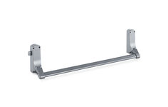
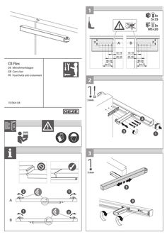
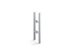
Push-bar IQ Bar 101
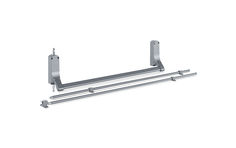
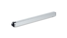
Push-bar IQ Bar 102

… Bar 300 Series Panic Exit Hardware 143801-01 GB Installation instructions IQ Bar 300 Series Table of Contents … IQ Bar 361 / IQ Bar 361 AL / IQ Bar 391 … IQ Bar 362 V / IQ Bar 362 V AL / IQ Bar 392 V / IQ Bar 364 DL … IQ Bar 363 V / IQ Bar 393 V … 18 IQ Bar 300 Series … Product description The GEZE IQ Panic Exit hardware devices are designed to give instant escape, when required, by a touch-bar panic device for either standard or flush doors on single or double doors, and can be operated from the outside of the door by an outside access device. When the outside access device is locked the door can still be released from the inside. … Product overview IQ Bar 300 Series … Hardware range Alarm Wide (900-1200mm) BAR 361 BAR 361 AL Standard IQ Bar 361 AL Touch Bar … Point Panic Latch with alarm IQ Bar 391 Touch Bar … Point Panic Latch BAR 362 V AL BAR 362 V IQ Bar 361 Touch Bar … Point Panic Latch IQ Bar 362 V AL Touch Bar … Point Pullman Catches IQ Bar 392 V Touch Bar … Point Pullman Catches BAR 363 V IQ Bar 362 V Touch Bar … Point Pullman Catches IQ Bar 363 V Touch Bar … Point Pullman Catches IQ Bar 393 V Touch Bar … Point Pullman Catches IQ Bar 363 DL Touch Bar … Point Double Door Set for Rebated Double Doors for doors up to 900mm IQ Bar 361+ IQ Bar 362 V … BAR 362 V BAR 362 V BAR 362 V BAR 361 Double Door Sets IQ Bar 364 DL Touch Bar … Point Double Door Set for Non Rebated Double Doors for doors up to 900mm IQ Bar 362 V + IQ Bar 362 V IQ Bar 300 Series … Product overview Panic device contents list IQ Bar 361 IQ Bar 361 AL IQ Bar 391 Touch bar … IQ Bar 362 V IQ Bar 362 V AL IQ Bar 392 V … IQ Bar 363 V IQ Bar 393 V … for flush doors 406 B (supplied with various packers) (Note: Suppliied only with double door unit IQ Bar 363 DL otherwise supplied separately) Latch keep … Fixing and installation IQ Bar 300 Series Screw D Pozi Countersunk Head Machine Screws (M4 x 6mm) … 1 (Note: Suppliied assembled, securing end cap cover) Screw pack(s) contents list IQ Bar 361 IQ Bar 361 AL IQ Bar 391 IQ Bar 362 V IQ Bar 362 V AL IQ Bar 392 V IQ Bar 363 V IQ Bar 393 V Screw A Pozi Countersunk Head Wood Screw (No.8 x … 6 „Push bar to open“ sign … Introduction àà àà àà àà àà àà àà These exit devices are suitable for right or left hand opening doors. The 900mm device is for doors measuring up to 2440mm high and 700 to 900mm wide. The 1200mm device is for doors measuring up to 2440mm high and 900 to 1200mm wide. The door must weigh no more than 200kg and be mounted in a good-quality well-made frame. The door/doors should be checked to ensure correct hanging and freedom from binding. Ensure that no weather strips or fixings on the door or door frame stop the device from working properly. If the door is to be fitted with a device which allows you to open it from outside, read the instructions provided with that device. àà All measurements are in millimetres. àà For installation of double door sets refer to the instuctions of the relevant single door units. àà IQ Bar 363 V DL = IQ Bar 361 + IQ Bar 362 V àà IQ Bar 364 V DL = IQ Bar 362 V + IQ Bar 362 V … Step A: Fitting the touch-bar panic device Make sure you have everything on the panic device contents list and the screw pack contents list. Then get together everything you need for the job. You will need the following: àà Tape measure àà A pencil àà Sticky tape (to stick the templates to the door) àà Spirit level àà Pozi head screwdrivers (No.1 & No.2 blades) àà Bradawl àà A drill with 3mm and 19mm bits XX Remove the head cover from the touch bar by removing the two screws D (see diagram 1). Also remove the end cap by taking out the one screw E (see diagram 3). You must use the templates to make sure you fix all the parts of the device in the correct place. XX XX BAR 362 V These units can be fitted on a single door. IQ Bar 361 can be also fitted on the first opening (active) leaf of an IQ Bar 363 DL … point double door set for rebated double doors. In this case a revised fitting position for the unit is however required. BAR 361 IQ Bar 361 / IQ Bar 361 AL / IQ Bar 391 A … Fixing and installation BAR 361 IQ Bar 300 Series A Unit Centre Height: between 900mm & 1100mm Diagram … main fixing Ø3mm holes to suit the supplied wood screws. Drill the two Ø19mm x 16mm deep holes. IQ Bar 300 Series Diagram … (supplied in set IQ Bar 363 DL) on last opening door leaf with the ‘lip’ against edge of door. Centre the keep about the latch (which should be located in the recessed area against the plastic plug). Ensure the anti-tamper bolt (see diagram 2) is located against one of the flat areas on the latch keep. XX Using a bradawl mark the positions of the fixing holes. Drill the holes and fix in place using the screws provided with the keep (Screws B). Fit and adjust with the packers provided until the correct engagement is achieved. … against the side face of the frame. Centre the keep around the latch (which should be located in the recess against the plastic plug). Ensure the anti-tamper bolt (see diagram 2) is located against one of the flat areas on the latch keep. XX Using a bradawl, mark the positions of the screw holes. Drill the holes and fix the latch keep in place with two Screws A. Step C: Testing the operation & fitting the sign. XX Test the unit to ensure that when the touch bar is operated the door opens immediately and swings freely. When closed the centre latch engages fully in the keep and holds the door securely shut. XX Fit the green self adhesive ‘Push Bar to Open’ sign onto the door positioned immediately above the touch bar. IQ Bar 300 Series … Fixing and installation IQ Bar 362 V / IQ Bar 362 V AL / IQ Bar 392 V / IQ Bar 364 DL These units can be fitted on a single door. IQ Bar 362 V can be also fitted on the last opening (pasive) leaf of an IQ Bar 363 DL set for rebated double doors or on both leafs of an IQ Bar 364 DL set for non rebated double doors. Step A: Fitting the touch-bar panic device XX Make sure you have everything on the panic device contents list and the screw pack contents list. Then get together everything you need for the job. You will need the following: àà Tape measure àà A pencil àà Sticky tape (to stick the templates to the door) àà Spirit level àà Pozi head screwdrivers (No.1 & No.2 blades) àà Two 10mm Open Ended Spanners. àà Bradawl àà A drill with 3mm and 19mm bits àà A Hacksaw XX Remove the head cover from the touch bar by removing the two screws D (see diagram 1). Also remove the end cap by taking out the one screw E (see diagram 3). You must use the templates to make sure you fix all the parts of the device in the correct place. XX XX A Unit centre height: between 900mm & 1100mm Diagram … main fixing Ø3mm holes to suit the supplied wood screws. Drill the Ø19mm hole 16mm deep. XX Repeat the process for the other leaf. IQ Bar 300 Series Diagram … Touch bar with Pullman catches and rod covers In case of using an outside access device (OAD) pause the installation of the panic device and fit the OAD before continuing with the installation. Refer to chapter “Outside Access Device (OAD)“. Fitting the touchbar(s): XX Fit the touchbar to the door. Ensure that the touchbar’s protruding drive spindle (see diagram 1) is located in Ø19mm x 16mm deep clearance hole. Secure to the door with … IQ Bar 300 Series XX XX Accurately cut one rod cover to this length. From the measured dimension add 20mm and cut the rod to this length. Bottom Pullman rod & cover: XX Repeat the steps above but accurately measuring between the edges on the Touchbar & the bottom Pullman catch. Step D: Fitting the rods & rod covers. XX Refit the Head cover and End Cap and secure using the screws as removed in the first step. XX Screw one off Nut F onto each end of both threaded Rods. Approximately 30mm from each end. Fitting Top Rod: XX Screw one end of the rod into the top Pullman catch until it clears the top bracket on the Touchbar. XX Unscrew the rod from the Pullman catch guiding it through the hole in the top bracket until it is approximately 10mm through the top bracket. At this point hold the top rod up to ensure that the Pullman catch is fully extended. XX XX XX Fixing and installation XX Using a bradawl mark the positions of the fixing holes. Drill the holes and fix in place using the screws provided with the keep (Screws B). Fit and adjust with the packers provided until the correct engagement is achieved. For: standard doors, rebated & non-rebated double doors: XX Position Pullman keep … on the frame / sill / floor as appropriate with the flat face against the door. Centre the keep about the latch (which should be located in the recessed area against the plastic plug). XX Using a bradawl mark the positions of the fixing holes. Drill the holes and fix in place using the screws provided with the keep (Screws A). Step F: Testing the operation & fitting the sign. XX Test the unit to ensure that when the touch bar is operated the door opens immediately and swings freely and when the door is closed the pullman catches engage fully in the keeps and hold the door securely closed. XX Fit the green self adhesive ‘Push bar to open’ sign onto the door positioned immediately above the touch bar. Screw one Nut F onto the end of the rod until it contacts the top bracket. Screw the 2nd Nut F onto the other side of the top bracket. Use … IQ Bar 300 Series IQ Bar 363 V / IQ Bar 393 V Step A: Fitting the touch-bar panic device XX Make sure you have everything on the panic device contents list and the screw pack contents list. Then get together everything you need for the job. You will need the following: àà Tape measure àà A pencil àà Sticky tape (to stick the templates to the door) àà Spirit level àà Pozi head screwdrivers (No.1 & No.2 blades) àà Two 10mm Open Ended Spanners. àà Bradawl àà A drill with 3mm and 19mm bits àà A Hacksaw XX Remove the head cover from the touch bar by removing the two screws D (see diagram 1). Also remove the end cap by taking out the one screw E (see diagram 3). A Unit centre height: between 900mm & 1100mm Diagram … (Note: Use No.1 Pozi screwdriver) IQ Bar 300 Series Step B: Positioning and fitting the pullman catches. XX Remove the covers from the Pullman catches by removing the two screws D. XX Follow the instructions on Template … Touch bar with Pullman catches and rod covers Step C: Preparing the rods & rod covers. XX Referring to Template … against the side face of the frame. Centre the keep around the latch (which should be located in the recess against the plastic plug). Ensure the anti-tamper bolt (see diagram 2) is located against one of the flat areas on the latch keep XX Using a bradawl, mark the positions of the screw holes. Drill the holes and fix the latch keep in place with two Screws A. 14 IQ Bar 300 Series Step F: Testing the operation & fitting the sign. XX Test the unit to ensure that when the touch bar is operated the door opens immediately and swings freely and when the door is closed the centre latch and the pullman catches engage fully in the keeps and hold the door securely closed. XX Fit the green self adhesive ‘Push bar to open’ sign onto the door positioned immediately above the touch bar. … Outside Access Devices (Overview) There are two outside access devices (OAD) available: àà 300 L EC with Lever àà 300 K with Knob. The cylinder in the 300 L EC is changeable. The cylinder In the 300 K cannot be removed. Both of these outside access devices provide a lockable entry facility for doors fitted with IQ Bar 300 Series. Outside access devices always allow immediate exit regardless of whether the device is locked or unlocked. For double door installations with rebated meeting door stiles, the outside access device must be fitted on the first opening (last closing) door leaf. … Fitting the 300 K Step A: Positioning the device XX Working on the inside face of the door establish the position for the Outside Access Device. Single door: Centreline 37mm from the jamb. Flush door: Centreline 26mm from thejamb. Double doors: Centreline 25mm from the last opening door edge. XX Choose the correct template (template 5). Stick the template to the door as explained on that template. Align the template with the touch bar mounting holes and the clearance hole. Mark the positions of the inner top and bottom outside access device mounting holes. XX Drill three 5mm dia fixing holes (Holes B) XX Drill 19mm dia. clearance (Hole A) hole through the door. XX Countersink all three holes (Holes B) 10mm dia. for timber doors (when using the dished washers, for steel doors countersink to suit) on the inside door face. XX Counterbore all three holes (Holes B) from the OUTSIDE of the door 8mm dia. x 22mm deep. (see diagram 1) XX Prepare three M4 c’sk. head screws. Measure the door thickness, subtract 8mm and cut to length (see diagram 1). XX Prepare the drive spindle. Measure the door IQ Bar 300 Series XX XX XX XX Fixing and installation thickness add12mm to this and cut the drive spindle to this length. Fit the drive spindle into the square hole (see diagram 1). Using the dished washers (for timber doors) and two screws. Secure the outside access device to the door using the top inner and bottom centre holes only. Ensure that drive spindle is positioned centrally in the clearance hole and that the body of the outside access device is square to the edge of the door. Install the touch bar panic device. Locate the drive spindle. Use the remaining screw in the top outer fixing hole to secure both the touch bar and the outside access device. Complete the installation of the touch bar as described in the appropriate fitting procedure sheet. Step B: Testing the device Once the panic device has been installed test for free and correct operation of both the outside access device & the panic device/s. … o‘clock position as required). XX Insert the lever set pin provided through the hole in the back plate situated below the square drive location. Engage the thread and thighten fully. Step B: Re-setting the outside access device’s lever if set the wrong way in error (see diagram 2) XX Operate the cylinder lock key in an anti-clockwise direction to lock the unit (disengage the mechanism).Remove the key. XX Remove the backplate assembly (4 screws).Taking care not to displace the drive spindle from the lever boss. XX Remove the lever set pin (if it has been fitted). XX Look inside the body. Locate the lever drive pin. Depress the spring loaded lever drive pin to disengage the lever from, the sprung disc. XX Gently rotate the lever towards the correct po- XX XX sition until the drive lever drive pin re-engages. Taking care not to rotate the sprung disc. Continue to move the lever against the spring pressure until it’s just past the horizontal position and the lever drive pin engages in the new position. Fit the lever set pin to retain the lever in its new position. Refit the backplate assembly (4 screws). Line up the setting marks on the drive spindle with those on the backplate assembly. Test the operation of the unit. Step C: Changing the cylinder lock To change the cylinder follow the steps below. XX Remove the backplate assembly (4 screws). Taking care not to displace the drive spindle from the lever boss. XX Remove the existing cylinder by removing the screw. Take care not to lose the tubular spacer. XX Place the new cylinder lock flat on the back plate locate the tubular spacer between the cylinder and fixing tag and secure with the screw. XX Refit the backplate assembly and test operation. Step D: Positioning the device XX Working on the inside face of the door establish the position for the Outside Access Device. Single door: Centreline 37mm from the jamb. Flush door: Centreline 26mm from the jamb. Double doors: Centreline 25mm from the last opening door edge. XX Choose the correct template (template 4). Stick 15 Fixing and installation the template to the door as explained on that template. Align the template with the touchbar mounting holes and the clearance hole. Mark the positions of the inner top and bottom outside access device mounting holes. For added security a 5th mounting screw (hole F on the template) is provided for an additional outside access device fixing. However this extra screw is only hidden from view when used in conjunction with two & three point panic units,but is visible on the inside face of the door on single point (latch) versions. XX XX XX XX XX XX XX XX XX XX XX XX Drill four / five (see above) 5mm dia fixing holes (Holes B, C, D, E & F). Drill the 19mm dia. clearance hole through the door (Hole A). Countersink the two inner holes (and the 5th hole if used) 10mm dia. for timber doors (when using the dished washers, for steel doors countersink to suit) on the inside door face (Holes C, D & F). Counterbore both top holes (see diagram A) from the OUTSIDE 8mm dia. x 22mm deep (Holes B & C). Prepare two (short) M4 c’sk. head screws for the top mounting holes (see diagram 3). Measure the door thickness, subtract 5mm and cut to length. Prepare two/three (long) M4 c’sk. head screws for the bottom mounting holes (see diagram 3). Take the door thickness dimension, add 12mm and cut to length. Prepare the drive spindle. Measure the door thickness add 12mm to this and cut the drive spindle to this length. Fit the drive spindle in to the square hole (see diagram 3). Ensure that the setting marks are in alignment. Using dished washers (for timber doors) and one short an one long c’sk. head screw. Secure the outside access device using the inner holes only. Ensure that the drive spindle is positioned centrally in the clearance hole and that the body of the outside access device is square to the edge of the door. Install the touch bar panic device. Locate the drive spindle. Use the two remaining screws, short (top) and long (bottom) in the outer fixing holes to secure both the touch bar and the outside access device. Complete the installation of the touchbar as described in the appropriate fitting procedure sheet. Step H: Testing the device Once the panic device has been installed test for free and correct operation of both the outside access device & the panic device/s. 16 IQ Bar 300 Series IQ Bar 300 Series … (standard projection) Panic exit devices should be used in situations where there is restricted width for escape, or where the doors to be fitted with the Panic exit devices are not able to open beyond 90°. àà Where an exit device is to be fitted to a glazed door, it is essential that the glazing is tempered or laminated glass. àà Different fixings are available (on request) for fitting these Panic exit devices to metal doors, etc. Timber fixings are supplied as standard. àà None of our Panic exit devices are intended for use on double action (double swing) doors. àà The fixing instructions should be carefully followed during installation. The instructions should be passed on by the installer to the user. àà The Touchbar should normally be installed at a height of between 900 mm and 1100 mm from the finished floor level, when the door is in the secured position. Where it is known that the majority of the occupants of the premises will be young children, consideration should be given to reducing the height of the bar / operating element accordingly. àà The correct size of Touchbar should be installed to provide the maximum effective length. Note: The size of the Touchbars operating element should be a minimum of 60% of the width of the door face. àà The latches and keepers should be fitted to provide secure engagement. Care should be taken to ensure that no projection of the latches, when in the withdrawn position, can prevent the door swinging freely. àà Where exit devices are to be fitted to double doorsets with rebated meeting stiles and self closing devices, a door coordinator device in accordance with EN 1158 should be fitted to ensure the correct closing sequence of the doors. This recommendation is particularly important with regard to fire/smoke resisting door assemblies. àà No additional devices for securing the door in the closed position should be fitted. This does not preclude the installation of self closing devices. àà If a door closing device is to be used to return the door to the closed position, care should be taken not to impair the use of the doorway by the young, elderly and infirm. àà Any keepers or protection plates provided should be fitted in order to ensure compliance with EN1125. àà The provided sign which reads; “Push bar to open” should be affixed on the inside face of the door immediately above the Touchbar. 17 Maintenance instructions … IQ Bar 300 Series Maintenance instructions It is important that all a panic and emergency exit hardware devices are inspected and maintained properly to ensure safety is maintained when exiting a building in any situation. Once the device is fitted regular maintenance is recommended. Weekly: XX Make sure the Exit Device functions correctly. XX Any fixings that have worked loose should be re-secured XX Any damaged components should be replaced. XX Ensure there are no obstructions which prevent the panic unit from functioning correctly. Every three months: XX Check for wear, any visible worn components should be replaced. The following is the routine maintenance procedure as recommended by EN1125 XX Inspect and operate the exit device to ensure that all components are in a satisfactory working condition. If possible using a force gauge, measure and record the operating forces to release the exit device. XX Ensure the keeper(s) is (are) free from obstruction. XX Check that the exit device is lubricated in accordance with the producer’s instructions. XX Check that no additional locking devices have been added to the door since its original installation. XX Check periodically that all components of the system are still correct in accordance with the list of approved components originally supplied with the system. XX Check periodically that the operating element is correctly tightened and, If possible using a force gauge, measure the operating forces to release the exit device. Check that the operating forces have not changed significantly from the operating forces recorded when originally installed. … PREPARE SQUARE SPINDLE: MEASURE DOOR THICKNESS ADD 14mm. CUT SPINDLE TO THIS LENGTH. PREPARE THREE SCREWS: MEASURE DOOR THICKNESS SUBTRACT 8mm. CUT SCREWS TO THIS LENGTH. HOLES B: DRILL Ø5mm THROUGH THE DOOR. ON INSIDE FACE OF DOOR COUTERSINK Ø10mm. FROM OUTSIDE FACE OF DOOR COUTERBORE Ø8 x 22mm DEEP. HOLE A: DRILL ONE HOLE Ø19mm THROUGH THE DOOR. USE THIS WAY UP ON INSIDE FACE OF DOOR FOR FITTING 300 K KNOB OUTSIDE ACCESS DEVICE B A B B USE FOR RIGHT HAND DOOR EDGE OF LEFT HAND STANDARD DOOR FRAME (FOR REFERANCE) LISTED ACCESSORIES Only the accessories listed below can be used with this product range. The use of any other accessory may invalidate the relevant products EN1125 CE certification. PRODUCT No. DESCRIPTION 406A OUTSIDE ACCESS DEVICES Knob operated Outside Access Device Lever operated Outside Access Device with Euro cylinder KEEPS Pullman Latch Keep for flush doors / frames 406B Centre Latch Keep for rebated double / flush doors 3402 Standard Pullman Latch Keep 4401 Standard Centre Latch Keep 300 K 300 L EC COMPATIBILITY use with all GEZE IQ Bar 300 series range Use with: IQ Bar 362 V, IQ Bar 392 V, IQ Bar 363 V, IQ Bar 393 V, IQ Bar 362 AL, IQ Bar 363 DL, IQ Bar 364 DL Use with: IQ Bar 361, IQ Bar 391, IQ Bar 363 V, IQ Bar 393 V As supplied with IQ Bar 363 DL IQ Bar 362 V, IQ Bar 392 V, IQ Bar 363 V, IQ Bar 393 V, IQ Bar 362 AL, IQ Bar 363 DL, IQ Bar 364 DL As supplied with: IQ Bar 361, IQ Bar 391, IQ Bar 363 V, IQ Bar 393 V Unless other wise stated compatibility is assumed with all the various suffixed variations (e.g. ‘AL’ & ‘MS’) of the basic product. CE MARKING All devices are intended for use on single / double outward opening route escape doors, fire / none-fire rated dependant on device (see below). Where fire rated; devices are certified for use on the following door assemblies for the stated times: 60 minutes on Timber door assemblies (doorsets to EN 1634-1 Codes: TT, ITT and ITC). 240 minutes on Steel door assemblies (doorsets to EN 1634-1 Codes: IMM, and MM). Minimum resistance for all devices: a maximum pulling force of 1000N was achieved against the fixings under the abuse test. Below is the CE marking information for the entire range. Applicable products are clearly listed below their relevant markings. 1121 EN 1125: 2008 PANIC EXIT DEVICES … Projection. Field of Door application: Category A (Single & Double) Suitable for use on fire / smoke doors. Applicable to Products: IQ Bar 361, IQ Bar 391, IQ Bar 362 V, IQ Bar 392 V, IQ Bar 363V, IQ Bar 393 V, IQ Bar 361 AL, IQ Bar 362 AL, IQ Bar 363 DL, IQ Bar 364 DL GEZE GmbH, Reinhold-Vöster-Str. 21-29, D-71229 Leonberg The product codes listed above refer to the Exidor OEM product model numbers. These are as appear on the main installation instruction sheet. It is taken as read that these also include all the suffixed versions of the basic models for: ‘AL’ (alarm), ‘MS’ (microswitch) where applicable. These are as listed on the relevant CE certificates. FDMI-0035-400-1 Issue2 24 25 26 27 Germany GEZE GmbH Niederlassung Süd-West Tel. +49 (0) 7152 203 594 E-Mail: leonberg.de@geze.com GEZE GmbH Niederlassung Süd-Ost Tel. +49 (0) 7152 203 6440 E-Mail: muenchen.de@geze.com GEZE GmbH Niederlassung Ost Tel. +49 (0) 7152 203 6840 E-Mail: berlin.de@geze.com GEZE GmbH Niederlassung Mitte/Luxemburg Tel. +49 (0) 7152 203 6888 E-Mail: frankfurt.de@geze.com GEZE GmbH Niederlassung West Tel. +49 (0) 7152 203 6770 E-Mail: duesseldorf.de@geze.com GEZE GmbH Niederlassung Nord Tel. +49 (0) 7152 203 6600 E-Mail: hamburg.de@geze.com GEZE Service GmbH Tel. +49 (0) 1802 923392 E-Mail: service-info.de@geze.com Austria GEZE Austria E-Mail: austria.at@geze.com www.geze.at Hungary GEZE Hungary Kft. E-Mail: office-hungary@geze.com www.geze.hu Scandinavia – Sweden GEZE Scandinavia AB E-Mail: sverige.se@geze.com www.geze.se Baltic States – Lithuania / Latvia / Estonia E-Mail: baltic-states@geze.com Iberia GEZE Iberia S.R.L. E-Mail: info.es@geze.com www.geze.es Scandinavia – Norway GEZE Scandinavia AB avd. Norge E-Mail: norge.se@geze.com www.geze.no Benelux GEZE Benelux B.V. E-Mail: benelux.nl@geze.com www.geze.be www.geze.nl India GEZE India Private Ltd. E-Mail: office-india@geze.com www.geze.in Scandinavia – Denmark GEZE Danmark E-Mail: danmark.se@geze.com www.geze.dk Bulgaria GEZE Bulgaria - Trade E-Mail: office-bulgaria@geze.com www.geze.bg Italy GEZE Italia S.r.l E-Mail: italia.it@geze.com www.geze.it Singapore GEZE (Asia Pacific) Pte, Ltd. E-Mail: gezesea@geze.com.sg www.geze.com China GEZE Industries (Tianjin) Co., Ltd. E-Mail: chinasales@geze.com.cn www.geze.com.cn GEZE Engineering Roma S.r.l E-Mail: italia.it@geze.com www.geze.it South Africa GEZE South Africa (Pty) Ltd. E-Mail: info@gezesa.co.za www.geze.co.za GEZE Industries (Tianjin) Co., Ltd. Branch Office Shanghai E-Mail: chinasales@geze.com.cn www.geze.com.cn GEZE Industries (Tianjin) Co., Ltd. Branch Office Guangzhou E-Mail: chinasales@geze.com.cn www.geze.com.cn GEZE Industries (Tianjin) Co., Ltd. Branch Office Beijing E-Mail: chinasales@geze.com.cn www.geze.com.cn France GEZE France S.A.R.L. E-Mail: france.fr@geze.com www.geze.fr Korea GEZE Korea Ltd. E-Mail: info.kr@geze.com www.geze.com Poland GEZE Polska Sp.z o.o. E-Mail: geze.pl@geze.com www.geze.pl Romania GEZE Romania S.R.L. E-Mail: office-romania@geze.com www.geze.ro Russia OOO GEZE RUS E-Mail: office-russia@geze.com www.geze.ru Switzerland GEZE Schweiz AG E-Mail: schweiz.ch@geze.com www.geze.ch Turkey GEZE Kapı ve Pencere Sistemleri E-Mail: office-turkey@geze.com www.geze.com Ukraine LLC GEZE Ukraine E-Mail: office-ukraine@geze.com www.geze.ua United Arab Emirates/GCC GEZE Middle East E-Mail: gezeme@geze.com www.geze.ae United Kingdom GEZE UK Ltd. E-Mail: info.uk@geze.com www.geze.com GEZE GmbH Reinhold-Vöster-Straße 21–29 71229 Leonberg Germany Tel.: 0049 7152 203