Search filter
25 results found
… 1005 * AREAS OF APPLICATION For the connection to GEZE control panels Ceiling mounting Can be used in areas with dust and steam Heat detector for GEZE SHEV control panels AREAS OF APPLICATION For the connection to GEZE control panels Ceiling mounting Can be used in areas with dust and steam GEZE GmbH Reinhold-Vöster-Straße 21–29 D-71229 Leonberg TEL +49 7152 203-0 2026-08-22T02:56:54Z WEB www.geze.de Mail info.de@geze.com Product data sheet | Page … WM 1005 * PRODUCT FEATURES Reacts when alarm temperature is exceeded LED for status display Tested in accordance with EN 54 Safety and reliability confirmed by VdS certification TECHNICAL DATA Productname WM 1005 * VARIANTS / ORDER INFO Designation Description WM 1005 heat detector * Ceiling-mounted detector for GEZE SHEV control panels. VdS approved and EN 54 tested, incl. base. IdentNo. EAN Colour 112878 4042938128780 white RAL 9016 Dimensio ns 40 mm * The products designated above may vary in form, type, characteristics, function, or availability depending on the country. Please get in touch with your GEZE contact person if you have any questions. GEZE GmbH Reinhold-Vöster-Straße 21–29 D-71229 Leonberg TEL +49 7152 203-0 2026-08-22T02:56:54Z WEB www.geze.de Mail info.de@geze.com
Download (.PDF | 421 KB)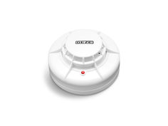
Heat differential detector WM 1005
… 1005/24 V DC EN Wiring diagram Symbols and means of representation Important information and technical notes are especially highlighted to explain correct operation. Symbol Meaning means "Important Information"; Information on avoiding material damage, understanding a concept or optimising workflows. Austria GEZE Austria GmbH E-Mail: austria.at@geze.com Baltic States GEZE GmbH Baltic States office E-Mail: office-latvia@geze.com GEZE Scandinavia AB avd. Norge E-Mail: norge.se@geze.com GEZE Industries (Tianjin) Co., Ltd. Branch Office Beijing E-Mail: chinasales@geze.com.cn GEZE Finland E-Mail: finland.se@geze.com GEZE Denmark E-Mail: danmark.se@geze.com France GEZE France S.A.R.L. E-Mail: france.fr@geze.com Hungary GEZE Hungary Kft. E-Mail: office-hungary@geze.com Iberia GEZE Iberia S.R.L. E-Mail: info@geze.es Singapore GEZE (Asia Pacific) Pte. Ltd. E-Mail: gezesea@geze.com.sg South Africa DCLSA Distributors (Pty.) Ltd. E-Mail: info@gezesa.co.za Switzerland GEZE Schweiz AG E-Mail: schweiz.ch@geze.com India GEZE India Private Ltd. E-Mail: office-india@geze.com Turkey GEZE GmbH Türkiye - İstanbul E-Mail: office-turkey@geze.com Italy GEZE Italia S.r.l E-Mail: italia.it@geze.com Ukraine Repräsentanz GEZE Ukraine TOV E-Mail: office-ukraine@geze.com GEZE Engineering Roma S.r.l E-Mail: roma@geze.biz United Arab Emirates/GCC GEZE Middle East E-Mail: geze@emirates.net.ae Benelux GEZE Benelux B.V. E-Mail: benelux.nl@geze.com Poland GEZE Polska Sp.z o.o. E-Mail: geze.pl@geze.com Bulgaria GEZE Bulgaria - Trade E-Mail: office-bulgaria@geze.com Romania GEZE Romania S.R.L. E-Mail: office-romania@geze.com GEZE GmbH P.O.Box 1363 71229 Leonberg Germany Tel.: 0049 7152 203-0 Fax: 0049 7152 203-310 www.geze.com United Kingdom GEZE UK Ltd. E-Mail: info.uk@geze.com 153191-02 Brief description The heat difference detector WM 1005 recognises open fires with and without smoke development. It records the ambient temperature and reacts when the triggering values specified in accordance with EN 54 Part
Download (.PDF | 375 KB)GEZE TS 5000 E-ISM BG DE Gleitschiene für Bandgegenseite mit integrierter Schließfolgeregelung und elektrischer Feststellung GB Guide rail for push side with integrated closing sequence control and electrical hold-open device FR Bras à coulisse avec régulation intégrée de fermeture en cascade et arrêt électrique pour montage côté opposé aux paumelles 115835-03 TS 5000 E-ISM BG Zu diesem Dokument … Zu diesem Dokument Diese Anleitung beschreibt die Montage und den Anschluss sowie die Inbetriebnahme der GEZE TS 5000 E-ISM BG Gleitschiene. … Produktbeschreibung Diese Gleitschiene ist für die Montage an zweiflügeligen Feuer- und Rauchschutztüren zugelassen. Die Anlage enthält elektrische Feststellungen für beide Türflügel, sowie eine integrierte Schließfolgeregelung. Wird bei geöffneten und in der elektrischen Feststellung eingerasteten Türflügeln der Gangflügel geschlossen, wird die elektrische Feststellung des Standflügels abgeschaltet. Der Gangflügel bleibt in seiner Warteposition, bis der Standflügel geschlossen ist und über die Schließfolgeregelung den Gangflügel freigibt. Bei Stromunterbrechung löst die elektrische Feststellung aus und die Türen schließen selbsttätig. Wenn der Standflügel einer zweiflügeligen Tür mit Brand- und/oder Rauchschutzeigenschaften geöffnet werden kann, ohne dass der Gangflügel in die Mindestwarteposition gelangt, ist eine möglichst einstellbare Mitnehmerklappe wie die GEZE Mitnehmerklappe CBflex einzusetzen um die Funktion der Schließfolgeregelung sicherzustellen. … Weitere Dokumente Im Lieferumfang der Komponenten sind jeweils weitere Unterlagen zur Montage bzw. zum Anschluss der Anlage enthalten. Bitte diese zu beachten. … Symbole und Darstellungsmittel Warnhinweise In dieser Anleitung werden Warnhinweise verwendet, um Sie vor Sach- und Personenschäden zu warnen. XX Lesen und beachten Sie diese Warnhinweise immer. XX Befolgen Sie alle Maßnahmen, die mit dem Warnsymbol und Warnwort gekennzeichnet sind. Warnsymbol Warnwort GEFAHR – VORSICHT Bedeutung Gefahren für Personen. Nichtbeachtung führt zu Tod oder schweren Verletzungen. Informationen zur Vermeidung von Sachschäden, zum Verständnis oder zum Optimieren der Arbeitsabläufe. Weitere Symbole und Darstellungsmittel Um die korrekte Bedienung zu verdeutlichen, sind wichtige Informationen und technische Hinweise besonders herausgestellt. Symbol Bedeutung bedeutet „Wichtiger Hinweis“ bedeutet „Zusätzliche Information“ XX … Symbol für eine Handlung: Hier müssen Sie etwas tun. XX Halten Sie bei mehreren Handlungsschritten die Reihenfolge ein. Produkthaftung Gemäß der im Produkthaftungsgesetz definierten Haftung des Herstellers für seine Produkte sind die in dieser Broschüre enthaltenen Informationen zu beachten. Die Nichtbeachtung entbindet den Hersteller von seiner Haftungspflicht. … Sicherheitshinweise àà Montage, Inbetriebnahme und Reparaturen sind durch einen Fachbetrieb auszuführen. àà Nur GEZE Originalteile für Reparaturarbeiten verwenden. àà Eigenmächtige Veränderungen an der Anlage schließen eine Haftung von GEZE für daraus resultierende Schäden aus. àà Bei Anwendung an Feuer- und Rauchschutzabschlüssen sind die länderspezifischen Vorschriften zu beachten. àà Für den elektrischen Anschluss und die Inbetriebnahme das Dokument „Anleitung zur Montage, Inbetriebnahme, Bedienung und Wartung der GEZE Feststellanlage FA GC“ beachten. DE … TS 5000 E-ISM BG … Lieferumfang Lieferumfang Abb.: … GF SF … 2 … 4 … 6 … 8 … Blende Gangflügel 10 Blende Standflügel 11 Mittelblende 12 Sichtkappe 13 Elektrische-Feststellung GF 14 Elektrische-Feststellung SF 15 Drahtseilumlenkung 16 Auslösehebel Schrauben, Anschlagschablone und Zubehörbeutel (ohne Abbildung) Gangflügel Standflügel ISM Gleitschiene Gangflügel ISM Gleitschiene Standflügel Drahtseil für Auslöser Auslöser Gleithebel Gleitstein Endkappe Gangflügel Endkappe Standflügel … Montage, Befestigung … Bohrbild TS 5000 mit E-ISM BG-Gleitschiene für Direktbefestigung oder Befestigung mit Montageplatte. A 140 160±0,2 122±1 Ø 15 mm, Stromzuführung (24 V DC) 140 440 122±1 160±0,2 A 38 44±0,1 110 135±0,2 160±0,2 11±1 440 A 140 135±0,2110 160±0,2 737,5±0,2 440±0,2 ±0,2 65±1 16±0,2 ±0,2 140 11±1 135±0,2110 160±0,2 440 A 140 737,5±0,2 440±0,2 ±0,2 10±0,5 10±0,5 11±1 A 10±0,5 122±1160±0,2 440 5±1 140 737,5±0,2 440±0,2 16±0,2 65±1 110 135±0,2 160±0,2 44±0,1 38 140 ±0,2 10±0,5 737,5±0,2 440±0,2 140 160±0,2122±1 Abb.: … .1 DE … Montage, Befestigung TS 5000 E-ISM BG XX Befestigungslöcher für Schließer und Gleitschiene nach Anschlagschablone anzeichnen/bohren, ggf. Gewinde M5 schneiden. XX Zusätzliche Bohrung (A) für Stromzuführung 24V DC anbringen. Für den Fall, dass dieses Produkt in einer Feststellanlage zum Einsatz kommt beachten Sie bitte auch das Dokument „Anleitung zur Montage, Inbetriebnahme, Bedienung und Wartung der GEZE Feststellanlage FA GC“. … Gleitschienen und Enkappen montieren Abb.: … .1 XX Standflügel-Kabel 24 V der elektrischen Feststellung seitlich aus der Standflügelgleitschiene herausnehmen (1.). XX Distanzstücke an der Gang- und Standflügelgleitschiene ausrichten (2.). XX Gleitschiene befestigen (3.) (Anzugsmoment … Nm). XX Endkappe am Gangflügel ausrichten und anschrauben (4.) (Anzugsmoment … Nm). XX Endkappe am Standflügel aufschieben (5.) XX Türschließer nach Anleitung befestigen (6.). Alle Schraubmomente sind ggf. bauseitig anzupassen. … Standflügel-Kabel 24 V anschließen Rot =’+’ Weiß = ’–’. Abb.: … .1 XX Standflügel-Kabel 24 V der elektrischen Feststellung zur Anschlussklemme führen. Kabel bei Bedarf mit Klebe- band fixieren (1.). XX Überschüssiges Kabel auf ca. 40 mm kürzen (2.). XX Kabel an Klemme anschließen (3.). DE … TS 5000 E-ISM BG … Montage, Befestigung 24 V Versorgungskabel anschließen Abb.: … .1 XX Bauseitiges 24V Versorgungskabel zur Anschlussklemme führen (1.). XX Überschüssiges Kabel auf ca. 40 mm kürzen (2.). XX Kabel an Klemme anschließen (3.). … Drahtseil mit Auslöser verbinden XX Spannschraube und Kontermutter am Spannteil 12 mm zurückschrauben (1.). XX Kugel am Drahtseil in den Auslösehebel einhängen (2.). XX Drahtseil in Trichter einführen (3.). XX Spannteil auf Drahtseil fädeln (4.). XX Spannteil einführen und Drahtseil durch Langloch fädeln (5.). XX Drahtseilumlenkung auf Drahtseil schieben (6.). Abb.: … .1 (Abb. … .2) XX Klemmschraube lösen (1.). XX Drahtseil mit Drahtseilumlenkung in Langloch einfädeln (2.). XX An der Klemmschraube vorbei durchfädeln und aus dem Langloch herausführen (3.). XX Drahtseil auf Anschlag spannen und Klemmschraube anziehen (4.). XX Auslösehebel montieren (5.). XX Anschlagschrauben einschrauben (6.). XX Spannteil wieder entspannen (7.) Spannschraube einschrauben (Kontermutter noch nicht anziehen!). XX Drahtseil auf 30–50 mm Überstand zur Außenkante Gleitschiene kürzen (8.). DE … TS 5000 E-ISM BG Montage, Befestigung 6. M3x10 7. 4. 6. M3x10 -50 2. 3. 30 8. 5. 1. 4. M6x14 SW5 Abb.: … .2 … Gleithebel am Standflügel montieren und mit Gleitstein verbinden Im Lieferzustand behindert die Türkante das korrekte Aufsetzen des Gleithebels auf den Schließer. Die Kerbe im Sechskant des Schließers muss in einer Flucht mit dem Gleithebel liegen. Abb.: … .1 XX Schließzeitventil schließen (1.). XX Gleithebel aufsetzen (2.). XX Gleithebel ca. 45° drehen um die Kerbe zu positionieren (3.). XX Gleithebel wieder abnehmen (4.). Nun kann der Gleithebel passend zur Kerbe aufgesetzt werden. XX Gleithebel mit Kerbe ausrichten und aufsetzen (5.). XX Gleithebel anschrauben (Anzugsmoment 14 Nm) (6.). XX Gleithebel mit Gleitstein verbinden (Anzugsmoment: … Nm) (7.). XX Schließzeitventil wieder öffnen (8.). DE … TS 5000 E-ISM BG … Montage, Befestigung Auslöser und Sperre einstellen XX Achten Sie darauf, dass das Drahtseil nicht eingeklemmt wird. Bei korrekter Einstellung müssen die Scheibe und die Kerbe in einer Flucht liegen. XX Abstand zwischen Scheibe und Kerbe + - messen (1.). XX Drahtseil um “X” spannen (2.). àà … Umdrehung der Stellschraube = ~1 mm Weg XX Einstellung mit Kronenmutter sichern (3.). “X” 1. + 3. 2. Abb.: … .1 … Gleithebel am Gangflügel montieren und mit Gleitstein verbinden Die Montage des Gleithebels an den Gangflügel erfolgt in gleicher Weise wie am Standflügel (siehe Kapitel … ). 7. Abb.: … .1 … Funktionssicherung der Schließfolgeregelung positionieren Abb.: … .1 DE … Montage, Befestigung TS 5000 E-ISM BG XX Mitnehmer maximal herausziehen (1.). XX Schrauben der Anschlagstange lösen, max. 1/2 Umdrehung (2.). Anschlagstange darf nicht unter den Mitnehmer kippen. XX Anschlagstange herausziehen (3.). àà Abstand Kante-Sperre und Anschlag: ca. 30 mm XX Gangflügeltür schließen (4.). Anschlagstange für Funktionssicherung der Schließfolgeregelung ist positioniert. XX Gangflügeltür öffnen (5.). XX Schrauben der Anschlagstange festziehen (6.). … Einstellen der elektrischen Feststellungen Darstellung Gangflügel. XX Türflügel auf den gewünschten Feststellwinkel öffnen und festsetzen (1.). XX Kabelschutzfolien aus der Gleitschiene entfernen (2.). XX Klemmschrauben der elektrischen Feststellung lösen (3.). XX Elektrische Feststellung verschieben, bis Rastkeil am Gleitstein anliegt (4.). XX Elektrische Feststellung festschrauben (5.). XX Zur Vermeidung von Schlaufen, Kabel straffen und Kabelschutz direkt am Ende der elektrischen Feststellung anlegen (6.). XX Loses Kabel im Kabelschutz und freien Bereich verstauen (7.). XX Sichtbares Kabel mit der Kabelschutzfolie fixieren (8.). VORSICHT! XX Freigängigkeit der Wippe nach oben prüfen! 9. Abb.: … .1 Bei Bedarf kann die Haltekraft eingestellt werden (9.). Nach EN 1155 soll bei einer Tür mit 90°-Feststellung das Ausrückmoment 40 Nm - 120 Nm betragen. … Blenden montieren VORSICHT! XX Kabel nicht quetschen. DE … TS 5000 E-ISM BG Erstinbetriebnahme 4. 1. 2. 4. 3. 2. C = B - 1189 mm C = D - 10 mm B D 35 (5) C 35 (5) A GF SF Abb. … .1 XX Ausbrechteil am Standflügel für Auslösehebel entfernen (1.). XX Gangflügelblende und Standflügelblende aufklipsen (2.). XX Die ablängbare mittlere Blende “A” auf das Maß “C” kürzen (Abb. … .1). XX Abgelängte Mittelblende aufklipsen (3.). XX Sichtkappen zwischen den Blenden einsetzen (4.). … Erstinbetriebnahme … Ersteinschaltung, Test XX Strom einschalten. XX Gangflügel öffnen und in elektrischen Feststellung einrasten. XX Standflügel öffnen und in elektrischen Feststellung einrasten. XX Gangflügel von Hand aus der elektrischen Feststellung ausdrücken. Standflügel schließt selbstständig. Gangflügel bleibt in der Warteposition der Schließfolgeregelung stehen und schließt ebenfalls, wenn der Standflügel geschlossen ist. … Abnahmeprüfung (nur bei Einsatz in einer Feststellanlage) Nach dem betriebsfertigen Einbau der Anlage ist am Verwendungsort deren einwandfreie Funktion und vorschriftsmäßige Installation durch eine Abnahmeprüfung festzustellen. Abnahmeprüfung durch autorisiertes Fachpersonal siehe Dokument „Anleitung zur Montage, Inbetriebnahme, Bedienung und Wartung der GEZE Feststellanlage FA GC“. … Wartung, Pflege, Reparatur Eine regelmäßige Wartung ist erforderlich. Für weitere Informationen beachten Sie bitte das Dokument „Anleitung zur Montage, Inbetriebnahme, Bedienung und Wartung der GEZE Feststellanlage FA GC“. … Technische Daten Technische Daten siehe Dokument „Anleitung zur Montage, Inbetriebnahme, Bedienung und Wartung der GEZE Feststellanlage FA GC“. DE … About this document … TS 5000 E-ISM BG About this document These instructions describe the installation and commissioning of the GEZE TS 5000 E-ISM BG guide rail. … Product description This slide rail is approved for installation on double-leaf fire and smoke protection doors. The system contains electrical hold-open devices for both door leaves and an integrated closing sequence control. If the moving leaf is closed with the door leaves opened and engaged in the electrical hold-open device, the electrical hold-open device of the fixed leaf is swiched off. The moving leaf remains in its waiting position until the fixed leaf is closed and releases the moving leaf via the closing sequence control. In case of power interruption, the electrical hold-open device is triggered and the doors closes automatically. If a double leaf smoke or fire protection door can be opened via the passive leaf, without opening the active leaf up to the minimal waiting position of the sequence control, a preferably adjustable carry bar such as the GEZE CBflex must be used to ensure the functionality of the door sequence control unit. … Related documents Additional documents for the installation and connection of the system are supplied with every component. Please follow these instructions. … Key to symbols Warning In these instructions, warnings are used to warn against material damage and injuries. XX Always read and observe these warnings. XX Follow all instructions marked with the warning symbol and the word WARNING. Warning symbol – Warning Meaning DANGER Danger for people. Non-observance can result in death or serious injuries. CAUTION Information to prevent damage to property and to understand and optimise workflow. Further symbols used in these instructions Important information and technical notes are emphasised to illustrate the correct operation. Symbol Meaning means “Important note“ means “Additional information” XX … Symbol for a user action. Here you have to take an action. XX Observe the sequence if there are several action steps. Product liability According to the definition of manufacturer‘s liability for his products in the Product Liability Act, the information contained in this brochure are to be followed. Ignoring this information absolves the manufacturer from his liability. … Safety instructions àà Installation, commissioning and repairs must be performed by a specialist. àà Use only GEZE original parts for repair work. àà Unauthorised modifications of the system excludes GEZE from the liability for any resulting damage. àà When used in fire and smoke barriers, all local regulations should be observed. àà Please observe the document “Instructions for Installation, Commissioning, Operation and Maintenance of the GEZE Hold-Open Device FA GC“. GB … Scope of delivery TS 5000 E-ISM BG … Scope of delivery Fig.: … GF SF … 2 … 4 … 6 … 8 … Moving-leaf cover panel 10 Fixed-leaf cover panel 11 Middle cover panel 12 Inspection cap 13 Electrical hold-open device for movig leaf 14 Electrical hold-open device for fixed leaf 15 Wire cable redirection 16 Trigger lever Screws, Fitting template and accessories bag (without illustration) Moving leaf Fixed leaf ISM Moving-leaf guide rail ISM Fixed-leaf guide rail Wire cable for trigger Trigger Sliding lever Sliding block Moving-leaf end cap Fixed-leaf end cap … Mounting and securing … Drilling template TS 5000 with E-ISM BG-guide rail for direct fixing or fixing with a mounting plate. A 140 160±0,2 122±1 Bore Ø 15 mm, Power supply (24 V DC) 140 440 122±1 160±0,2 A 38 44±0,1 110 135±0,2 160±0,2 11±1 440 A 140 135±0,2110 160±0,2 737,5±0,2 440±0,2 ±0,2 65±1 16±0,2 ±0,2 140 11±1 135±0,2110 160±0,2 440 A 140 737,5±0,2 440±0,2 ±0,2 10±0,5 10±0,5 11±1 A 10±0,5 122±1160±0,2 440 5±1 140 737,5±0,2 440±0,2 16±0,2 65±1 110 135±0,2 160±0,2 44±0,1 38 140 ±0,2 10±0,5 737,5±0,2 440±0,2 140 160±0,2122±1 Fig.: … .1 GB … Mounting and securing TS 5000 E-ISM BG XX Mark out and drill fixing holes for door closer and guide rail using fitting template or cut M5 thread if necessary. XX Drill additional hole (A) for 24V DC power supply. In case this product is in use with an hold-open device, please observe the document “Instructions for Installation, Commissioning, Operation and Maintenance of the GEZE Hold-Open Device FA GC” as well. … Mount guide rail and end caps Fig.: … .1 XX Remove 24 V fixed-leaf cable of the electrical hold-open device sideways from fixed-leaf guide rail (1.). XX Align spacers on moving and fixed-leaf guide rails (2.). XX Fix guide rails in place (tightening torque: … Nm) (3.). XX Align end caps on moving leaf and screw on (4.) (tightening torque: … Nm). XX Slide on cover at fixed leaf (5.) XX Mount door closer according to the mounting instructions (6.). All screwing torques are to be adjusted on site, if necessary. … Connecting 24 V fixed-leaf cable red =’+’ white = ’–’. Fig.: … .1 XX Route 24 V fixed-leaf cable of electrical hold-open device to the supply terminal. Secure cable with adhesive tape if necessary (1.). XX Shorten excess cable to approx. 40 mm (2.). XX Connect cable to terminal (3.). GB … TS 5000 E-ISM BG … Mounting and securing Connecting 24 V power supply cable Fig.: … .1 XX Guide 24 V power supply cable provided on site to the supply terminals (1.).. XX Shorten excess cable to 40 mm (2.). XX Connect cable (3.). … Connecting wire cable to trigger XX Unscrew set screw and lock nut 12 mm at clamping part (1.). XX Suspend ball on wire cable in the trigger lever (2.). XX Guide wire cable into funnel (3.). XX Thread clamping part onto wire cable (4.). XX Insert clamping part and thread wire cable through oblong hole (5.). XX Push wire cable redirection onto wire cable (6.). Fig.: … .1 (Fig. … .2) XX Loosen clamping screw (1.). XX Thread wire cable with wire cable redirection into oblong hole (2.). XX Thread past the clamping screw and guide out the oblong hole (3.). XX Tension wire cable firmly and tighten clamping screw (4.). XX Mount trigger lever (5.). XX Screw in stop screws (6.). XX Loosen clamping part again (7.) Screw in set screw (do not tighten lock nut yet!). XX Shorten wire cable to an excess of 30–50 mm to the outer edge of the guide rail. (8.). GB … Mounting and securing TS 5000 E-ISM BG 6. M3x10 7. 4. 6. M3x10 -50 2. 3. 30 8. 5. 1. 4. M6x14 SW5 Fig.: … .2 … Mount sliding lever to moving leaf and connect with sliding block In the delivery condition, the door edge hinders the correct fitting of the sliding lever on the door closer. The notch must be placed in the hexagonal bolt of the door closer in alignment with the sliding lever. Fig.: … .1 XX Close closing-time valve (1.). XX Set sliding lever in place (2.). XX Turn sliding lever about 45° to position the notch (3.). XX Remove sliding lever (4.). Now the sliding lever can be appropriately attached to the notch. XX Align and fit sliding lever with notch (5.). XX Fix sliding lever (tightening torque 14 Nm) (6.). XX Connect sliding lever to sliding block (tightening torque: … Nm) (7.). XX Open closing-time valve again (8.). GB … Mounting and securing TS 5000 E-ISM BG … Adjusting trigger and block XX Ensure that the wire cable is not clamped. When set correctly, the disc and the marking must be in line. XX Measure distance between disc and + - notch (1.). XX Tension wire cable by “X” (2.). àà one rotation of set screw = approx. … mm distance XX Secure setting with lock nut (3.). “X” 1. + 3. 2. Fig.: … .1 … Mount sliding lever to moving leaf and connect with sliding block Mounting of the sliding lever to the moving leaf occurs in the same manner as with the fixed leaf (see Section … ). 7. Fig.: … .1 … Positioning the function saveguard of the integrated closing sequence control Fig.: … .1 GB … Mounting and securing TS 5000 E-ISM BG XX Pull out driver as far as possible (1.). XX Loosen screws of stop rod (max. ½ rotation) (2.). Stop rod may not pass under driver.. XX Pull out stop rod (3.). àà Distance between edge block and stop is approx. 30 mm XX Close moving leaf (4.). Stop rod for function safeguard of the integrated closing sequence control is in position. XX Open moving leaf (5.). XX Tighten screws of stop rod (6.). … Adjusting electrical hold-open device Moving leaf is shown. XX Open door leaf to desired hold-open angle and fix it there (1.). XX Remove cable protection foils from guide (2.). XX Loosen clamping screws of electrical hold-open device (3.). XX Move electrical hold-open device until catch contacts sliding block (4.). XX Screw down electrical hold-open device securely (5.). XX To prevent loops from forming, tighten cable and fasten cable protection at hold open device end (6.). XX Stow away (7.) loose cable in the cable protection and free area. XX Secure exposed cable with the cable protection film (8.). CAUTION! XX Check free upward movement of the rocker! 9. Fig.: … .1 If necessary, the holding force can be adjusted (9.). According to EN 1155, the release torque should amount to 40 Nm - 120 Nm for a door with 90° hold- open angle. … Mounting cover panel CAUTION! XX Do not pinch cable. GB … Initial operation TS 5000 E-ISM BG 4. 1. 2. 4. 3. 2. C = B - 1189 mm C = D - 10 mm B D 35 (5) C 35 (5) A GF SF Fig. … .1 XX Remove break-off section on fixed leaf for trigger lever (1.). XX Clip on moving-leaf cover panel and fixed-leaf cover panel (2.). XX Shorten adjustable-size middle cover panel “A” to size “C” (Fig. … .1). XX Clip on middle cover panel (3.). XX Insert inspection caps between cover panels (4.). … Initial operation … First Operation and Function Test XX Switch on power. XX Open moving leaf and engage in electrical hold-open device.XX XX Open fixed leaf and engage in electrical hold-open device.XX XX Push moving leaf out of electrical hold-open device. Fixed leaf closes automatically. Moving leaf remains in waiting position of closing sequence control and also closes when fixed leaf is closed. … Testing for acceptance (only for use in a hold-open device) An acceptance test must be carried out in order to ascertain the correct function and installation according to the regulations once the installation has been completed on site. Acceptance test to be performed by authorised personnel; see “Instructions for Installation, Commissioning, Operation and Maintenance of the GEZE Hold-Open Device FA GC”. … Maintenance, servicing, repairs Regular servicing has to be carried out. For more information on this, please observe the document “Instructions for Installation, Commissioning, Operation and Maintenance of the GEZE Hold-Open Device FA GC”. … Technical Data For technical data, please observe the document “Instructions for Installation, Commissioning, Operation and Maintenance of the GEZE Hold-Open Device FA GC”. GB … Concernant le présent document … TS 5000 E-ISM BG Concernant le présent document Le présent manuel décrit le montage et la mise en service ainsi que le raccordement du bras à coulisse GEZE TS 5000 E-ISM BG. … Description du produit Cette glissière est homologuée pour être montée sur des portes anti-feu et anti-fumée à vantail unique. L‘installation comprend des arrêts électriques pour les deux battants de porte, ainsi qu‘une régulation intégrée de fermeture en cascade. Si le battant mobile est fermé alors que les battants de porte étaient ouverts et l‘arrêt électrique enclenché, l‘arrêt électrique du battant fixe se déconnecte. Le battant mobile reste dans sa position d‘attente jusqu‘à ce que le battant fixe soit fermé et que la régulation de fermeture en cascade libère le battant mobile. En cas de panne électrique, le dispositif de blocage électrique se déclenche et les portes se verrouille automatiquement. Si une porte à deux vantaux coupe-feu et/ou pare-fumée peut être ouverte par le vantail fixe, sans ouvrir le vantail de service au moins jusqu’à la position d’attente, un dispositif anti-chevauchement ajustable doit être utilisé, comme le dispositif GEZE CBflex, afin d’assurer le bon fonctionnement du contrôle de la fermeture. … Autres documents L‘emballage contenant les composants comporte d‘autres documents pour le montage ou le branchement de l‘installation. Il convient de les respecter. … Symboles et moyens de représentation Mises en garde Ce manuel contient des mises en garde pour vous protéger des dommages personnels et matériels. XX Lisez et observez toujours ces mises en garde. XX Observez toutes les mesures identifiées par le symbole et le mot de mise en garde. Symbole de Mot de mise mise en garde en garde – Signification DANGER Dangers pour les personnes. Le non respect peut entraîner la mort ou des blessures graves. ATTENTION Informations destinées à éviter les dommages matériels, à une meilleure compréhension ou à l‘optimisation des processus de travail. Autres symboles et moyens de représentation Pour illustrer l‘utilisation correcte, les informations et consignes techniques importantes sont présentées de sorte à attirer l‘attention. Symbole Signification signifie « Remarque importante » signifie « Information complémentaire » XX … Symbole pour une action : ici vous êtes invité à exécuter une action. XX Lors de plusieurs étapes d‘action, respectez l‘ordre prescrit. Responsabilité du produit Conformément à la responsabilité du fabricant pour ses produits définie dans la loi sur la responsabilité civile des produits, les informations contenues dans la présente brochure doivent être respectées. Le non-respect délie le fabricant de son obligation de responsabilité. … Consignes de sécurité àà Le montage, la mise en service et les réparations doivent être effectués par une entreprise spécialisée. àà Utiliser uniquement des pièces GEZE d‘origine pour les travaux de réparation. àà Toute modification du propre chef effectuée sur l‘installation exclut la responsabilité de GEZE pour les dommages en résultant. àà Il convient de respecter les dispositions nationales en vigueur en cas d‘utilisation sur des portes anti-feu et anti-fumée. àà Pour le raccordement électrique et la mise en service, observer les indications figurant dans le document « Instructions de montage, mise en service, utilisation et maintenance de l’installation de blocage GEZE FA GC ».. FR … Contenu de la livraison TS 5000 E-ISM BG … Contenu de la livraison Fig.: … GF Battant mobile Battant fixe ISM Bras à coulisse du battant mobile ISM Bras à coulisse du battant fixe Câble pour dispositif de déclenchement Dispositif de déclenchement Levier coulissant Coulisseau Capuchon du battant mobile Capuchon du battant fixe SF … 2 … 4 … 6 … 8 … Montage, fixation … Gabarit de perçage … 10 11 12 13 14 Cache du battant mobile Cache du battant fixe Cache central Embout Arrêt électrique du battant mobile Arrêt électrique du battant fixe 15 16 Renvoi du câble Levier de déclenchement Vis de fixation, gabarit de butée et sachet d‘accessoires (sans illustration) TS 5000 avec bras à coulisse E-ISM BG pour fixation directe ou fixation avec plaque de montage. A 140 160±0,2 122±1 Ø 15 mm, Alimentation en courant (24 V DC) 140 440 122±1 160±0,2 A 38 44±0,1 110 135±0,2 160±0,2 11±1 440 A 140 135±0,2110 160±0,2 737,5±0,2 440±0,2 ±0,2 65±1 16±0,2 ±0,2 140 11±1 135±0,2110 160±0,2 440 A 140 737,5±0,2 440±0,2 ±0,2 10±0,5 10±0,5 11±1 A 10±0,5 122±1160±0,2 440 5±1 140 737,5±0,2 440±0,2 16±0,2 65±1 110 135±0,2 160±0,2 44±0,1 38 140 ±0,2 10±0,5 737,5±0,2 440±0,2 140 160±0,2122±1 Fig.: … .1 FR … Montage, fixation TS 5000 E-ISM BG XX Repérer/percer les trous de fixation pour le ferme-porte et le bras à coulisse en suivant le gabarit de montage, couper le filet M5 si nécessaire. XX Réaliser le perçage supplémentaire (A) pour l‘alimentation électrique de 24V DC. En cas d’utilisation dans un dispositif de blocage, veuillez observer les indications figurant dans le document « Instructions de montage, mise en service, utilisation et maintenance de l’installation de blocage GEZE FA GC ». … Monter les bras à coulisse et les capuchons Fig.: … .1 XX Extraire le câble de 24 V du dispositif de blocage électrique latéralement de la glissière (1.). XX Aligner les pièces intercalaires sur les bras à coulisse du battant mobile et du battant fixe (2.). XX Fixer le bras à coulisse (couple de serrage … Nm) (3.). XX Aligner le capuchon sur le battant mobile et le visser (4.) (couple de serrage … Nm). XX Faire glisser le capuchon sur le flasque du vantail secondaire (5.) XX Fixer le ferme-porte selon la notice (6.). Tous les couples de serrage doivent être adaptés sur site. … Raccorder le câble 24 V du battant fixe Rouge =’+’ Blanc = ’–’. Fig.: … .1 XX Amener le câble 24 V du battant fixe à la borne de raccordement. Si nécessaire, fixer le câble avec du ruban adhésif (1.). XX Raccourcir le câble excédentaire à env. 40 mm (2.). XX Raccorder le câble à la borne (3.). FR … TS 5000 E-ISM BG … Montage, fixation Raccordement du câble d’alimentation 24 V Fig.: … .1 XX Tirer le câble réseau du chantier vers la borne (1.). XX Raccourcir le câble excédentaire à env. 40 mm (2.). XX Raccorder le câble à la borne (3.). … Relier le câble au dispositif de déclenchement XX Dévisser de 12 mm le tendeur de gaine et le contre-écrou (1.). XX Accrocher la bille du câble métallique dans le levier de déclenchement (2.). XX Introduire le câble métallique dans l’entonnoir du sélecteur (3.). XX Enfiler le tendeur de gaine sur le câble métallique (4.). XX Introduire le tendeur de gaine et enfiler le câble métallique à travers le trou oblong (5.). XX Faire glisser la gaine sur le câble métallique (6.). Fig.: … .1 (Fig. … .2) XX Desserrer le serre-câble (1.). XX Enfiler le câble métallique et la gaine dans le trou oblong (2.). XX Le faire passer à travers des serre-câbles et le sortir du trou oblong (3.). XX Tendre le câble métallique jusqu’à la butée et bloquer la vis du serre-câble (4.). XX Monter le levier de déclenchement (5.). XX Visser les vis de butée (6.). XX Desserrer le contre-écrou du serre-câble (7.) Visser le tendeur (ne pas serrer immédiatement le contre-écrou). XX Raccourcir le câble métallique en ne laissant dépasser que 30 à 50 mm (8.). FR … Montage, fixation TS 5000 E-ISM BG 6. M3x10 7. 4. 6. M3x10 -50 2. 3. 30 8. 5. 1. 4. M6x14 SW5 Fig.: … .2 … Relier le levier coulisseau au coulisseau du battant fixe Dans l’état de livraison, l’arête de porte empêche le placement correct du levier coulissant sur le fermeporte. L’encoche dans le six pans du ferme-porte doit être alignée sur le levier coulissant. Fig.: … .1 XX Visser à fond (sans forcer) la vis de réglage de la vitesse de fermeture (1.). XX Placer le levier coulissant (2.). XX Tourner le levier coulissant d’environ 45° afin de positionner l’encoche (3.). XX Enlever à nouveau le levier coulissant (4.). Le levier coulissant peut maintenant être mis en place en alignement avec l’encoche. XX Aligner le levier coulissant avec l’encoche et le placer (5.). XX Visser le levier coulissant (6.) (couple de serrage: 14 Nm). XX Relier le levier coulissant au coulisseau (7.) (couple de serrage: … Nm). XX Dévisser la vis de réglage de vitesse de fermeture (8.). FR … Montage, fixation TS 5000 E-ISM BG … Régler le dispositif de déclenchement et le blocage XX Veillez à ce que le câble métallique ne soit pas coincé. Pour un réglage correct, la plaque et l‘encoche doivent être alignées. XX Mesurer la distance entre la plaque et + - l‘encoche (1.). XX Tendre le câble métallique de “X” (2.). àà Un tour de la vis de tension = ~1 mm de déplacement XX Bloquer le réglage à l’aide du contre-écrou (3.). “X” 1. + 3. 2. Fig.: … .1 … Relier le levier coulisseau au coulisseau du battant mobile Le montage du bras à coulisse sur le vantail principal se fait de la même manière que pour le vantail secondaire (voir chapitre … ). 7. Fig.: … .1 … Positionner la protection fonctionnel de la régulation de fermeture en cascade Fig.: … .1 FR … Montage, fixation TS 5000 E-ISM BG XX Extraire l‘entraîneur jusqu‘à la butée (1.). XX Desserrer les vis de la tige de butée, max. 1/2 tour (2.). La tige de butée ne peut pas être en dessous de l‘entraîneur. XX Extraire la tige de butée (3.). àà Distance arête-blocage et butée env. 30 mm XX Fermer le battant mobile (4.). La tige de butée pour la protection fonctionnel de la régulation de fermeture en cascade est positionnée. XX Ouvrir le battant mobile (5.). XX Serrer les vis de la tige de butée (6.). … Réglage des arrêts électriques Représentation du battant mobile. XX Ouvrir le battant de porte à l‘angle d‘arrêt souhaité et le bloquer (1.). XX Enlever les films protecteurs de câbles du bras à coulisse (2.). XX Desserrer les vis de serrage de l‘arrêt électrique (3.). XX Déplacer l‘arrêt électrique jusqu‘à ce que le coin de verrouillage repose contre le coulisseau (4.). XX Visser l‘arrêt électrique (5.). XX Afin d‘éviter les boucles, tendre le câble et le placer le câble dans la protection à l‘extrémité de l‘arrêt (6.). XX Ranger les câbles détachés dans la gaine de câbles et libres (7.). XX Fixer le câble visible avec le film de protection de câble (8.). ATTENTION! XX Vérifier le libre fonctionnement de la bascule vers le haut! 9. Fig.: … .1 La force de maintien peut être réglée selon besoin (9.). Selon EN 1155, le couple de débrayage d‘une porte avec un blocage à 90° doit être de 40 Nm - 120 Nm. … Monter le cache ATTENTION! XX Ne pas écraser le câble. FR … Première mise en service TS 5000 E-ISM BG 4. 1. 2. 4. 3. 2. C = B - 1189 mm C = D - 10 mm B D 35 (5) C 35 (5) A GF SF Fig. … .1 XX Enlever la partie prédécoupée pour la fourchette de sélection côté vantail secondaire (1.). XX Clipser en place le cache du battant mobile et le cache du battant fixe (2.). XX Raccourcir à la cote „C“ le cache central „A“ pouvant être recoupé à longueur (Fig. … .1). XX Clipser le cache central (3.). XX Placer les embouts entre les caches (4.). … Première mise en service … Première mise en service et essais fonctionnels XX Mettre sous tension. XX Ouvrir le battant mobile et le verrouiller dans l‘arrêt élec trique. XX Ouvrir le battant fixe et le verrouiller dans l‘arrêt électrique. XX Pousser à la main le battant mobile hors de l‘arrêt électrique, le battant fixe se ferme automatiquement. Le battant mobile reste dans la position d‘attente de la régulation de fermeture en cascade et se ferme également lorsque le battant fixe est fermé. … Contrôle de réception (uniquement en cas d’utilisation dans un dispositif de blocage) Après avoir monté l’installation, pour qu’elle puisse être mise en service, il faut constater sur le lieu d’utilisation par un essai de réception, son bon fonctionnement et son installation réglementaire. Contrôle de réception par un technicien qualifiés agréé, voir document « Instructions de montage, mise en service, utilisation et maintenance de l’installation de blocage GEZE FA GC ». … Maintenance, entretien, réparation Il faut procéder à une maintenance régulière. Pour de plus amples informations, veuillez observer les indications figurant dans le document « Instructions de montage, mise en service, utilisation et maintenance de l’installation de blocage GEZE FA GC ». … Charactéristiques techniques Pour les spécifications techniques voir le document « Instructions de montage, mise en service, utilisation et maintenance de l’installation de blocage GEZE FA GC ». FR … Notes/Notizen TS 5000 E-ISM BG TS 5000 E-ISM BG Notes/Notizen Germany GEZE Sonderkonstruktionen GmbH Planken … 97944 Boxberg-Schweigern Tel. +49 (0) 7930 9294 … Fax +49 (0) 7930 9294 10 E-Mail: sk.de@geze.com GEZE GmbH Niederlassung Süd-West Tel. +49 (0) 7152 203 594 E-Mail: leonberg.de@geze.com GEZE GmbH Niederlassung Süd-Ost Tel. +49 (0) 7152 203 6440 E-Mail: muenchen.de@geze.com GEZE GmbH Niederlassung Ost Tel. +49 (0) 7152 203 6840 E-Mail: berlin.de@geze.com GEZE GmbH Niederlassung Mitte/Luxemburg Tel. +49 (0) 7152 203 6888 E-Mail: frankfurt.de@geze.com GEZE GmbH Niederlassung West Tel. +49 (0) 7152 203 6770 E-Mail: duesseldorf.de@geze.com GEZE GmbH Niederlassung Nord Tel. +49 (0) 7152 203 6600 E-Mail: hamburg.de@geze.com GEZE Service GmbH Tel. +49 (0) 1802 923392 E-Mail: service-info.de@geze.com GEZE GmbH Reinhold-Vöster-Straße 21–29 71229 Leonberg Germany Austria GEZE Austria E-Mail: austria.at@geze.com www.geze.at Hungary GEZE Hungary Kft. E-Mail: office-hungary@geze.com www.geze.hu Scandinavia – Denmark GEZE Danmark E-Mail: danmark.se@geze.com www.geze.dk Baltic States GEZE GmbH Baltic States office E-Mail: office-latvia@geze.com www.geze.com Iberia GEZE Iberia S.R.L. E-Mail: info@geze.es www.geze.es Singapore GEZE (Asia Pacific) Pte, Ltd. E-Mail: gezesea@geze.com.sg www.geze.com Benelux GEZE Benelux B.V. E-Mail: benelux.nl@geze.com www.geze.be www.geze.nl India GEZE India Private Ltd. E-Mail: office-india@geze.com www.geze.in South Africa GEZE Distributors (Pty) Ltd. E-Mail: info@gezesa.co.za www.geze.co.za Italy GEZE Italia S.r.l E-Mail: italia.it@geze.com www.geze.it Switzerland GEZE Schweiz AG E-Mail: schweiz.ch@geze.com www.geze.ch GEZE Engineering Roma S.r.l E-Mail: roma@geze.biz www.geze.it Turkey GEZE Kapı ve Pencere Sistemleri E-Mail: office-turkey@geze.com www.geze.com Bulgaria GEZE Bulgaria - Trade E-Mail: office-bulgaria@geze.com www.geze.bg China GEZE Industries (Tianjin) Co., Ltd. E-Mail: chinasales@geze.com.cn www.geze.com.cn GEZE Industries (Tianjin) Co., Ltd. Branch Office Shanghai E-Mail: chinasales@geze.com.cn www.geze.com.cn GEZE Industries (Tianjin) Co., Ltd. Branch Office Guangzhou E-Mail: chinasales@geze.com.cn www.geze.com.cn GEZE Industries (Tianjin) Co., Ltd. Branch Office Beijing E-Mail: chinasales@geze.com.cn www.geze.com.cn France GEZE France S.A.R.L. E-Mail: france.fr@geze.com www.geze.fr Tel.: 0049 7152 203 … Fax.: 0049 7152 203 310 www.geze.com Poland GEZE Polska Sp.z o.o. E-Mail: geze.pl@geze.com www.geze.pl Romania GEZE Romania S.R.L. E-Mail: office-romania@geze.com www.geze.ro Russia OOO GEZE RUS E-Mail: office-russia@geze.com www.geze.ru Scandinavia – Sweden GEZE Scandinavia AB E-Mail: sverige.se@geze.com www.geze.se Scandinavia – Norway GEZE Scandinavia AB avd. Norge E-Mail: norge.se@geze.com www.geze.no Ukraine LLC GEZE Ukraine E-Mail: office-ukraine@geze.com www.geze.ua United Arab Emirates/GCC GEZE Middle East E-Mail: gezeme@geze.com www.geze.ae United Kingdom GEZE UK Ltd. E-Mail: info.uk@geze.com www.geze.com
Download (.PDF | 4 MB)… 1005 79 290 40 79 710 378 79 80 13 … holes 1005 Push button 1195 13 … 793 793 120 793 300 279 80 40 Cable inputs 14 TECHNICAL SPECS: Width, mm SB 250 Single pass 900 Mechanism Servodrive Standard housing Brushed SS AISI 304 Available housing Brushed SS AISI 316 Polished SS AISI 304 Polished SS AISI 316 Powder coated RAL THE SB 250 IS PERFECT FOR PROVIDING ACCESSIBLE BUT CONTROLLED PASSAGE. • Voltage: - from the AC (100-240)V, 50/60Hz; - from a DC source 12 V Solid glass top Solid Solidglass glasstop top 900 900 1000 990 604 Controlled by: 990 990 604 604 Instalation tamplate 1520 1520 78 78 78 78 620 78 380 380 886 886 78 186 337 54 54 54 1005 54 54 1005 1005 1313 1212holes holes 13 12 holes 1520 1520 120 120 886 1520 1520 54 1520 1520 80 150 30 inputs Cable Cable inputs … holes 21 TECHNICAL SPECS: Width, mm Available housing Brushed SS AISI 316 Polished SS AISI 304 Polished SS AISI 316 Powder coated RAL ELECTRICAL SPECS: • Voltage: - from the AC (100-240)V, 50/60Hz; - from a DC source 12 V 825 825 513 513 1075 1075 In the event of a power failure, drop arm function activates automatically. Controlled by: Access control system 825 513 790 812 The inclined scratch resistant glass top gives this turnstile a futuristic look making it a stylish architectural element to complement any modern interior. Equipped with an automatic bi-directional servo-drive mechanism with a robust locking system the OX S operates reliably and efficiently in high traffic flow locations. This model has a robust hub with stainless steel pods and a fully automatic anti-panic system. LED displays indicate direction of travel through the turnstile and can clearly determine the status of passage (Green – Access authorised, Red- Access denied and Blue – Standby mode). Brushed SS AISI 304 1075 ERGONOMIC DESIGN WITH STYLISH BODY LINES IS THE DEFINING FEATURE OF THIS TURNSTILE. Servo-driven Standard housing 812 OX S Single pass 600 Mechanism 790 790 380 200 200 376 200 Instalation Instalation tam plate tamplate 45 93 332 332 200 100 200 100 270 270 Instalation Cable inputs Cable inputs 332 40 40 40 50 45 93 380 60 25 600 41 50 376 380 45 376 200 100 93 Push button 270 22 TECHNICAL SPECS: OX M Width, mm Single pass 600 Mechanism ERGONOMICALLY DESIGNED WITH STYLISH LINES WITH AN EFFICIENT CONTROL SYSTEM, THE OX M IS IDEAL FOR TODAY’S CONTEMPORARY INTERIORS. Servo-driven Standard housing Brushed SS AISI 304 Available housing Brushed SS AISI 316 Polished SS AISI 304 Polished SS AISI 316 Powder coated RAL ELECTRICAL SPECS: • Voltage: - from the AC (100-240)V, 50/60Hz; - from a DC source 12 V The OX M is equipped with an automatic bi-directional servo-drive mechanism with a robust locking system and so operates reliably and efficiently in high traffic flow locations. This model also has an automatic anti-panic system; in an emergency, the arms are automatically lowered and users can freely pass through unhindered. The cabinet tops are made of a scratch-resistant black glass, which allows simple maintenance and long lasting aesthetics. LED displays indicate direction of travel through the turnstile and can clearly determine the status of passage (Green – Access authorised, Red- Access denied and Blue – Standby mode). 1075 1005 In the event of a power failure, drop arm function activates automatically. Controlled by: Access control system 1000 253 1005 Push button 1005 14 … holes 804 828 1075 1075 180 36 1005 516 1000 253 1000 253 Instalation tamplate 14 … holes 1005 909 30 90 180 809 60 25 600 41 14 … holes 36 36 Cable inputs 180 1005 23 TECHNICAL SPECS: OX XL Width, mm Single pass 600 Mechanism Servo-driven Standard housing Brushed SS AISI 304 Available housing Brushed SS AISI 316 Polished SS AISI 304 Polished SS AISI 316 Powder coated RAL OX XL IS A RELIABLE TURNSTILE WITH MAXIMUM INTEGRATED OPTIONS AND CONVENIENCE FOR EVERYONE. ELECTRICAL SPECS: The main feature is the “All-in-one” design; it is easy to include additional equipment - controllers, barcode scanners / fingerprint reader, coin acceptors, card reader, ticket printers etc. The waist-high tripod turnstile also has a place for advertising (LED backlight). It expands the range of objects for installing a turnstile and the inclined scratch resistant glass top gives this turnstile a futuristic look making it a stylish architectural element to compliment any interior. OX XL turnstiles have an automatic bidirectional servo-drive mechanism with a robust locking system and operate reliably and efficiently in high traffic flow locations. The OX XL also has a reliable hub with stainless steel pods and a fully automatic “anti-panic” system. 1800 • Voltage: - from the AC (100-240)V, 50/60Hz; - from a DC source 12 V 1075 In the event of a power failure, drop arm function activates automatically. Controlled by: 790 Access control system 147 349 Push button 253 1202 Instalat 14
Download (.PDF | 4 MB)GEZE TS 5000 R-ISM BG DE Gleitschiene für Bandgegenseite mit integrierter Schließfolgeregelung, Rauchschalter und elektrischer Feststellung GB Guide rail for push side with integrated closing sequence control, smoke detector and electrical hold-open device FR Bras à coulisse avec regulation intégrée de fermeture en cascade, commutateur de fumée et arrêt électrique pour montage côté opposé aux paumelles 144507-02 TS 5000 R-ISM BG Zu diesem Dokument … Zu diesem Dokument Diese Anleitung beschreibt die Montage und den Anschluss sowie die Inbetriebnahme der GEZE TS 5000 R-ISM BG Gleitschiene. … Produktbeschreibung … Weitere Dokumente … Symbole und Darstellungsmittel Diese Gleitschiene ist für die Montage an zweiflügeligen Feuer- und Rauchschutztüren zugelassen. Die Anlage enthält elektrische Feststellungen für beide Türflügel, die von einer integrierten Rauchschalterzentrale gesteuert werden sowie eine integrierte Schließfolgeregelung. Wird bei geöffneten und in der elektrischen Feststellung eingerasteten Türflügeln der Gangflügel geschlossen, wird die elektrische Feststellung des Standflügels abgeschaltet. Der Gangflügel bleibt in seiner Warteposition, bis auch der Standflügel geschlossen ist und über die Schließfolgeregelung den Gangflügel freigibt. Im Brandfall oder bei Netzausfall löst die elektrische Feststellung aus und die Türen schließen selbsttätig. Wenn der Standflügel einer zweiflügeligen Tür mit Brand- und/oder Rauchschutzeigenschaften geöffnet werden kann, ohne dass der Gangflügel in die Mindestwarteposition gelangt, ist eine möglichst einstellbare Mitnehmerklappe wie die GEZE Mitnehmerklappe CBflex einzusetzen um die Funktion der Schließfolgeregelung sicherzustellen. Im Lieferumfang der Komponenten sind jeweils weitere Unterlagen zur Montage bzw. zum Anschluss der Anlage enthalten. Bitte diese zu beachten. Warnhinweise In dieser Anleitung werden Warnhinweise verwendet, um Sie vor Sach- und Personenschäden zu warnen. XX Lesen und beachten Sie diese Warnhinweise immer. XX Befolgen Sie alle Maßnahmen, die mit dem Warnsymbol und Warnwort gekennzeichnet sind. Warnsymbol Warnwort GEFAHR – VORSICHT Bedeutung Gefahren für Personen. Nichtbeachtung führt zu Tod oder schweren Verletzungen. Informationen zur Vermeidung von Sachschäden, zum Verständnis oder zum Optimieren der Arbeitsabläufe. Weitere Symbole und Darstellungsmittel Um die korrekte Bedienung zu verdeutlichen, sind wichtige Informationen und technische Hinweise besonders herausgestellt. Symbol Bedeutung bedeutet „Wichtiger Hinweis“ bedeutet „Zusätzliche Information“ XX Symbol für eine Handlung: Hier müssen Sie etwas tun. XX Halten Sie bei mehreren Handlungsschritten die Reihenfolge ein. … Produkthaftung … Sicherheitshinweise DE … Gemäß der im Produkthaftungsgesetz definierten Haftung des Herstellers für seine Produkte sind die in dieser Broschüre enthaltenen Informationen zu beachten. Die Nichtbeachtung entbindet den Hersteller von seiner Haftungspflicht. àà Montage, Inbetriebnahme und Reparaturen sind durch einen Fachbetrieb auszuführen. àà Nur GEZE Originalteile für Reparaturarbeiten verwenden. àà Eigenmächtige Veränderungen an der Anlage schließen eine Haftung von GEZE für daraus resultierende Schäden aus. àà Bei Anwendung an Feuer- und Rauchschutzabschlüssen sind die länderspezifischen Vorschriften zu beachten. àà Für den elektrischen Anschluss und die Inbetriebnahme das Dokument „Anleitung zur Montage, Inbetriebnahme, Bedienung und Wartung der GEZE Feststellanlage FA GC“ beachten. TS 5000 R-ISM BG … Lieferumfang Lieferumfang Abb.: … GF SF … 2 … 4 … 6 … 8 … 10 11 12 13 14 15 16 Gangflügel Standflügel ISM Gleitschiene Gangflügel ISM Gleitschiene Standflügel Rauchschalter (verpackt) Elektrische-Feststellung GF Elektrische-Feststellung SF Drahtseil für Auslöser Auslöser … Montage, Befestigung … Bohrbild 17 Rauchschaltergehäuse 18 Resettaste 19 Gleitstein 20 Drahtseilumlenkung 21 Auslösehebel Schrauben, Anschlagschablone und Zubehörbeutel (ohne Abbildung) Gleithebel Netzteil mit Aufnahme Endkappe Blende Gangflügel Blende Standflügel Mittelblende Sichtkappe Schutzkappe Schaumstoffeinlage C A 160±0,2 122±1 140 122±1 160±0,2 5±1 C B 367,5±0,2 A C B A B Bohrung für Rauchschaltergehäuse Ø 15 mm, Stromzuführung 230 V AC C 38 44±0,1 0-5 440±0,2 A 5±1 140 110 135±0,2 160±0,2 367,5±0,2 0-5 440±0,2 10±0,5 135±0,2110 160±0,2 440±0,2 140 784,5±0,2 763,5±0,2 440±0,2 140 135±0,2110 160±0,2 784,5±0,2 763,5±0,2 440±0,2 65±1 16±0,2 B 140 10±0,5 367,5±0,2 A 10±0,5 C 0-5 B 440±0,2 10±0,5 122±1160±0,2 367,5±0,2 5±1 140 784,5±0,2 763,5±0,2 440±0,2 16±0,2 65±1 110 135±0,2 160±0,2 44±0,1 38 140 5±1 784,5±0,2 763,5±0,2 440±0,2 0-5 TS 5000 L mit R-ISM-Gleitschiene für Direktbefestigung oder Befestigung mit Montageplatte. 140 160±0,2122±1 Abb.: … .1 Ø 15 mm, Öffnung für Zusatzanschlüsse (optional) DE … TS 5000 R-ISM BG Montage, Befestigung XX Befestigungslöcher für Schließer und Gleitschiene nach Anschlagschablone anzeichnen/bohren, ggf. Gewinde M5 schneiden. XX Befestigungsloch (A) für Rauchschaltergehäuse anzeichnen/bohren, ggf. Gewinde M5 schneiden. XX Zusätzliche Bohrung (B) für Stromzuführung 230V anbringen. XX Bei Bedarf Öffnung für Zusatzanschlüsse (C) anbringen. WICHTIG Um ein einwandfreies Ansprechen des Rauchschalters zu gewährleisten, darf eine Distanz zwischen Oberkante Gleitschiene und Decke/Sturz von mindestens 10 mm nicht unterschritten werden! >10 mm Je nach Feststellanlage beachten Sie bitte auch das Dokument „Anleitung zur Montage, Inbetriebnahme, Bedienung und Wartung der GEZE Feststellanlage FA GC“. Abb.: … .2 … Gleitschiene und Netzteil montieren M5x45 5x55 M5x45 3. 5x55 M5x45 3. M5x45 5x55 3. GF 5x55 3. SF 1. 6. 6. 4. 5. M4x8 Abb.: … .1 XX Standflügel-Kabel 24 V der elektrischen Feststellung seitlich aus der Standflügelgleitschiene herausnehmen (1.). XX Distanzstücke an der Gang- und Standflügelgleitschiene ausrichten (2.). XX Gleitschiene befestigen (Anzugsmoment … Nm) (3.). XX Netzteil mit Aufnahme am Gangflügel ausrichten und anschrauben (4.) (Anzugsmoment … Nm). XX Endkappe am Standflügel aufschieben (5.). XX Türschließer nach Anleitung befestigen (6.). Alle Schraubmomente sind ggf. bauseitig anzupassen. … Rauchschaltergehäuse befestigen GEFAHR! Lebensgefahr durch elektrischen Stromschlag. Die elektrischen Anschlussarbeiten dürfen nur von Elektrofachkräften ausgeführt werden. Betriebsspannung: 230 V AC +10 % / –15 %, XX Stromzuführung unterbrechen. Die GEZE Feststellanlagen FA GC sind Geräte der Schutzklasse II Schutzart IP 20, nur für trockene Räume. Umgebungstemperatur -5 °C bis 50 °C. Die 230 V Zuleitung ist doppelt isoliert (mit Kabelmantel) mindestens … mm in den Anschlussraum einzuführen. Geräte der Schutzklasse II werden mit einem zweiadrigen Kabel NYM-O, 2x1,5 angeschlossen. Der Anschluss kann auch mit einem dreiadrigen Kabel NYM-J, 3x1,5 erfolgen. Der Schutzleiter darf dann nicht angeschlossen und muss dauerhaft isoliert werden (z. B. zusätzliche Lüsterklemme oder Schrumpfschlauch). DE … TS 5000 R-ISM BG Montage, Befestigung Bei Aufputzzuführung für das 230-V-Kabel einen Kabelschutz verwenden. Die aus der Wand stehenden Kabel für 230 V und für Zusatzanschlüsse durch die entsprechenden Öffnungen des Rauchschaltergehäuses führen! M5x45/5x55 Abb.: … .1 XX 230 V Netzkabel durch das Rauchschaltergehäuse führen und auf ca. 80 mm ablängen (1.). XX Rauchschaltergehäuse ausrichten und an Gangflügelgleitschiene und Türrahmen festschrauben (2.). … Standflügel-Kabel 24 V anschließen Rot =’+’ Weiß = ’–’. Abb.: … .1 XX Standflügel-Kabel 24 V der elektrischen Feststellung in der oberen Führung des Rauchschaltergehäuses verle- gen und zur Anschlussklemme führen. Kabel bei Bedarf mit Klebeband fixieren (1.). XX Überschüssiges Kabel auf ca. 40 mm kürzen (2.). XX Kabel an Klemme anschließen (3.). … Netzanschluss Abb.: … .1 XX Bauseitige Netzleitung mit Sicherung B10 absichern. XX Bauseitiges Netzkabel zur Klemme verlegen (2.) und anschließen (3.). XX Netzteil Zuleitung 230 V von der Klemme ausgehend verlegen (4.) und Überlänge am Netzteil verstauen. XX Deckel des Rauchschaltergehäuses schließen und verschrauben (5.). DE … Montage, Befestigung … TS 5000 R-ISM BG Kabel von Netzteil und Rauchschalter verlegen Abb.: … .1 XX 24 V Ausgangskabel vom Netzteil am Gangflügel in das Innere des Rauchschaltergehäuses verlegen (6.). Rot =’+’ Weiß = ’–’. XX Kabel 24 V der elektrischen Feststellung vom Gehäuseinneren zur Anschlussklemme führen (1.). Abb.: … .2 XX Kabel an Klemme anschließen (2.). XX Beide 24V Kabel mit Schaumstoffeinlage gegen Herausfallen schützen (3.). … Drahtseil mit Auslöser verbinden XX Spannschraube und Kontermutter am Spannteil 12 mm zurückschrauben (1.). XX Kugel am Drahtseil in den Auslösehebel einhängen (2.). XX Drahtseil in der unteren Führung des Rauchschaltergehäuses verlegen (3.). XX Drahtseil in Trichter einführen (4.). XX Spannteil auf Drahtseil fädeln (5.). XX Spannteil einführen und Drahtseil durch Langloch fädeln (6.). XX Drahtseilumlenkung auf Drahtseil schieben (7.). Abb.: … .1 (Abb. … .2) XX Klemmschraube lösen (1). XX Drahtseil mit Drahtseilumlenkung in Langloch einfädeln (2.). XX An der Klemmschraube vorbei durchfädeln und aus dem Langloch herausführen (3.). XX Drahtseil auf Anschlag spannen und Klemmschraube anziehen (4.). XX Auslösehebel montieren (5.). DE … TS 5000 R-ISM BG Montage, Befestigung XX Anschlagschrauben einschrauben (6.). XX Spannteil wieder entspannen (7.) Spannschraube einschrauben (Kontermutter noch nicht anziehen!). XX Drahtseil auf 30–50 mm Überstand zur Außenkante Gleitschiene kürzen (8.). M3x10 M3x10 M6x14 SW … Abb.: … .2 … Gleithebel am Standflügel montieren und mit Gleitstein verbinden Im Lieferzustand behindert die Türkante das korrekte Aufsetzen des Gleithebels auf den Schließer. Die Kerbe im Sechskant des Schließers muss in einer Flucht mit dem Gleithebel liegen. Abb.: … .1 XX Schließzeitventil schließen (1.). XX Gleithebel aufsetzen (2.). XX Gleithebel ca. 45° drehen um die Kerbe zu positionieren (3.). XX Gleithebel wieder abnehmen (4.). Nun kann der Gleithebel passend zur Kerbe aufgesetzt werden. XX Gleithebel mit Kerbe ausrichten und aufsetzen (5.). XX Gleithebel anschrauben (Anzugsmoment 14 Nm) (6.). XX Gleithebel mit Gleitstein verbinden (Anzugsmoment: … Nm) (7.). XX Schließzeitventil wieder öffnen (8.). DE … TS 5000 R-ISM BG Montage, Befestigung … Auslöser und Sperre einstellen XX Achten Sie darauf, dass das Drahtseil nicht eingeklemmt wird. Bei korrekter Einstellung müssen die Scheibe und die Kerbe in einer Flucht liegen. XX Abstand zwischen Scheibe und Kerbe + - messen (1.). XX Drahtseil um “X” spannen (2.). àà … Umdrehung der Stellschraube = ~1 mm Weg XX Einstellung mit Kronenmutter sichern (3.). 1. “X” + - 2. 3. Abb.: … .1 … Gleithebel am Gangflügel montieren und mit Gleitstein verbinden Die Montage des Gleithebels an den Gangflügel erfolgt in gleicher Weise wie am Standflügel (siehe Kapitel … ). Abb.: … .1 … Funktionssicherung der Schließfolgeregelung positionieren 4. 1. mm ~30 3. 2. (~½ ) 5. 6. GF Abb.: … .1 XX Mitnehmer maximal herausziehen (1.). XX Schrauben der Anschlagstange lösen, max. 1/2 Umdrehung (2.). DE … TS 5000 R-ISM BG Montage, Befestigung Anschlagstange darf nicht unter den Mitnehmer kippen. XX Anschlagstange herausziehen (3.). Abstand Kante-Sperre und Anschlag: ca. 30 mm XX Gangflügeltür schließen (4.). Anschlagstange für Funktionssicherung der Schließfolgeregelung ist positioniert. XX Gangflügeltür öffnen (5.). XX Schrauben der Anschlagstange festziehen (6.). … Blenden montieren VORSICHT! XX Kabel nicht quetschen. 5. 1. 4. 2. 5. 3. 2. C = B - 1189 mm C = D - 10 mm B D 35 (5) C 35 (5) A GF SF Abb. … .1 Wichtig: Rauchschalteröffnung der Mittelblende muss über der Messkammer des Rauchschalters sitzen. Bei Bedarf kann das Maß „D“ zwischen den Flügelblenden gemessen werden. XX Ausbrechteil am Standflügel für Auslösehebel entfernen (1.). XX Gangflügelblende und Standflügelblende aufklipsen (2.). XX Die ablängbare mittlere Blende “A” auf das Maß “C” kürzen (Abb. … .1). XX Abgelängte Mittelblende aufklipsen (3.). XX Schutzkappe aufklipsen (4.). XX Sichtkappen zwischen den Blenden einsetzen (5.). VORSICHT! XX Schutzkappe so aufsetzen, dass die Rauchschalteröffnung in der Blende verdeckt wird um den Innen- raum der Anlage vor Verschmutzung zu schützen. Schutzkappe muss bei Inbetriebnahme der Feststellanlage entfernt werden. DE … Erstinbetriebnahme … TS 5000 R-ISM BG Erstinbetriebnahme VORSICHT! Der Einbau des Rauchschalters darf erst kurz vor Inbetriebnahme erfolgen um unnötige Verschmutzungen zu vermeiden. Bei vorzeitigem Einbau besteht die Gefahr, dass der Rauchschalter durch den Baustaub verschmutzt wird. Dadurch kann die Lebensdauer des Rauchschalters erheblich verkürzt werden! … Blende entfernen XX Sichtkappen zwischen den Blenden entfernen (1.) / Schutzkappe entfernen (2.). XX Mittelblende und Gangflügelblende entfernen (3.) / Schaumstoffeinlage herausnehmen (4.). Abb.: … .1 … Einbau und Anschluss des Rauchschalters XX Rauchschalter einklipsen. Abb.: … .1 XX Kabel 24 V der elektrischen Feststellung (1) und des Netzteils (2) einstecken. XX Überschüssiges Kabel in der Netzteilaufnahme verstauen. XX Zusatzanschlüsse siehe separates Dokument „Anleitung zur Montage, Inbetriebnahme, Bedienung und Wartung der GEZE Feststellanlage FA GC“. Abb.: … .2 DE 10 TS 5000 R-ISM BG … Erstinbetriebnahme Einstellen der elektrischen Feststellungen Darstellung Gangflügel. XX Türflügel auf den gewünschten Feststellwinkel öffnen und festsetzen (1.). XX Kabelschutzfolien aus der Gleitschiene entfernen (2.). XX Klemmschrauben der elektrischen Feststellung lösen (3.). XX Elektrische Feststellung verschieben, bis Rastkeil am Gleitstein anliegt (4.). XX Elektrische Feststellung festschrauben (5.). XX Zur Vermeidung von Schlaufen, Kabel straffen und Kabelschutz direkt am Ende der elektrischen Feststellung anlegen (6.). XX Loses Kabel im Kabelschutz und freien Bereich verstauen (7.). XX Sichtbares Kabel mit der Kabelschutzfolie fixieren (8.). VORSICHT! XX Freigängigkeit der Wippe nach oben prüfen! 9. Abb.: … .1 Bei Bedarf kann die Haltekraft eingestellt werden (9.). Nach EN 1155 soll bei einer Tür mit 90°-Feststellung das Ausrückmoment 40 Nm - 120 Nm betragen. … Blenden montieren VORSICHT! XX Kabel nicht quetschen. Abb.: … .1 XX Mittelblende und Gangflügelblende aufklipsen (1.). Prüfen Sie, ob die Rauchschalteröffnung direkt über dem Rauchschalter sitzt. XX Sichtkappen zwischen den Blenden einsetzen (2.). DE 11 Wartung, Pflege, Reparatur … TS 5000 R-ISM BG Ersteinschaltung, Test XX Schutzkappe entfernen (falls noch nicht erfolgt). XX Strom einschalten. àà Betriebsanzeige leuchtet GRÜN und elektrische Feststellung ist bestromt. XX Türflügel in elektrische Feststellung einrasten. XX Resettaste am Rauchschalter betätigen. àà Betriebsanzeige leuchtet ca. … s GELB. àà Tür läuft zu. àà Danach leuchtet die Betriebsanzeige wieder GRÜN. … Funktionstest der E-Feststellung und Schließfolgeregelung XX Gangflügel öffnen und in elektrische Feststellung einrasten. XX Standflügel öffnen und in elektrische Feststellung einrasten. XX Gangflügel von Hand aus der elektrischen Feststellung ausdrücken. Standflügel schließt selbstständig. Gangflügel bleibt in der Warteposition der Schließfolgeregelung stehen und schließt ebenfalls, wenn der Standflügel geschlossen ist. … Abnahmeprüfung Nach dem betriebsfertigen Einbau der Anlage ist am Verwendungsort deren einwandfreie Funktion und vorschriftsmäßige Installation durch eine Abnahmeprüfung festzustellen. Abnahmeprüfung durch autorisiertes Fachpersonal siehe Dokument „Anleitung zur Montage, Inbetriebnahme, Bedienung und Wartung der GEZE Feststellanlage FA GC“. … Wartung, Pflege, Reparatur Die Einbaufirma muss den Betreiber der Anlage auf diesen Teil der Montageanleitung aufmerksam machen, und diese sowie die Benutzerinformation (Beipackzettel zum Türschließer) dem Betreiber aushändigen. Es ist eine regelmäßige Wartung durchzuführen. Für weitere Informationen beachten Sie bitte das Dokument „Anleitung zur Montage, Inbetriebnahme, Bedienung und Wartung der GEZE Feststellanlage FA GC“. DE 12 About this document TS 5000 R-ISM BG … About this document These instructions describe the installation and commissioning of the GEZE TS 5000 R-ISM BG guide rail. … Product description This slide rail is approved for installation on double-leaf fire and smoke protection doors. The system contains electrical hold-open devices for both door leaves, which are controlled by a smoke detector, and an integrated closing sequence control. If the moving leaf is closed with the door leaves opened and engaged in the electrical hold-open device, the electrical hold-open device of the fixed leaf is swiched off. The moving leaf remains in its waiting position until the fixed leaf is closed and releases the moving leaf via the closing sequence control. In case of fire or power failure, the electrical hold-open device is triggered and the doors closes automatically. If a double leaf smoke or fire protection door can be opened via the passive leaf, without opening the active leaf up to the minimal waiting position of the sequence control, a preferably adjustable carry bar such as the GEZE CBflex must be used to ensure the functionality of the door sequence control unit. … Related documents Additional documents for the installation and connection of the system are supplied with every component. Please follow these instructions. … Key to symbols Warning In these instructions, warnings are used to warn against material damage and injuries. XX Always read and observe these warnings. XX Follow all instructions marked with the warning symbol and the word WARNING. Warning symbol – Warning Meaning DANGER Danger for people. Non-observance can result in death or serious injuries. CAUTION Information to prevent damage to property and to understand and optimise workflow. Further symbols used in these instructions Important information and technical notes are emphasised to illustrate the correct operation. Symbol Meaning means “Important note“ means “Additional information” XX … Symbol for a user action. Here you have to take an action. XX Observe the sequence if there are several action steps. Product liability According to the definition of manufacturer‘s liability for his products in the Product Liability Act, the information contained in this brochure are to be followed. Ignoring this information absolves the manufacturer from his liability. … Safety instructions àà Installation, commissioning and repairs must be performed by a specialist. àà Use only GEZE original parts for repair work. àà Unauthorised modifications of the system excludes GEZE from the liability for any resulting damage. àà When used in fire and smoke barriers, all local regulations should be observed. àà Please observe the document “Instructions for Installation, Commissioning, Operation and Maintenance of the GEZE Hold-Open Device FA GC“. GB … Scope of delivery … TS 5000 R-ISM BG Scope of delivery Fig.: … GF SF … 2 … 4 Moving leaf Fixed leaf ISM Moving-leaf guide rail ISM Fixed-leaf guide rail Smoke switch (packed) Electrical hold-open device for moving leaf Electrical hold-open device for fixed leaf … 6 … 8 … 10 11 12 13 14 … Mounting and securing … Drilling template 15 Protective cap 16 Foam lining 17 Smoke switch housing 18 Reset button 19 Sliding block 20 Wire cable redirection 21 Trigger lever Screws, fitting template and accessories bag (without illustration) Wire cable for trigger Trigger Sliding lever Power pack with mounting End cap Moving-leaf cover panel Fixed-leaf cover panel Middle cover panel Inspection cap C A 160±0,2 122±1 140 122±1 160±0,2 5±1 C B 367,5±0,2 A C B A B GB … Bore for smoke switch housing Ø 15 mm, Power supply (230 V AC) C 38 44±0,1 0-5 440±0,2 A 5±1 140 110 135±0,2 160±0,2 367,5±0,2 0-5 440±0,2 10±0,5 135±0,2110 160±0,2 440±0,2 140 784,5±0,2 763,5±0,2 440±0,2 140 135±0,2110 160±0,2 784,5±0,2 763,5±0,2 440±0,2 65±1 16±0,2 B 140 10±0,5 367,5±0,2 A 10±0,5 C 0-5 B 440±0,2 10±0,5 122±1160±0,2 367,5±0,2 5±1 140 784,5±0,2 763,5±0,2 440±0,2 16±0,2 65±1 110 135±0,2 160±0,2 44±0,1 38 140 5±1 784,5±0,2 763,5±0,2 440±0,2 0-5 TS 5000 L with R-ISM guide rail for direct fixing or fixing with a mounting plate. 140 160±0,2122±1 Fig.: … .1 Ø 15 mm, Opening for additional connections (optional) Mounting and securing TS 5000 R-ISM BG XX Mark out and drill fixing holes for door closer and guide rail using fitting template or cut M5 thread if necessary. XX Mark/drill mounting hole (A) for smoke switch housing, if necessary cut M5 thread. XX Drill additional hole (B) for 230V power supply. XX If necessary, make opening for additional connections (C). IMPORTANT To guarantee correct functioning of the smoke detector, GEZE recommends that the distance between the upper edge of the smoke detector and the ceiling be at least 10 mm! >10 mm Depending on the hold-open device, please observe the document “Instructions for Installation, Commissioning, Operation and Maintenance of the GEZE HoldOpen Device FA GC” as well. Fig.: … .2 … Mount slide rail and power pack M5x45 5x55 M5x45 3. 5x55 M5x45 3. M5x45 5x55 3. GF 5x55 3. SF 1. 6. 6. 4. 5. M4x8 Fig.: … .1 XX Remove 24 V fixed-leaf cable of the electrical hold-open device sideways from fixed-leaf guide rail (1.). XX Align spacers on moving and fixed-leaf guide rails (2.). XX Fix guide rails in place (tightening torque: … Nm) (3.). XX Align cover with power pack on moving leaf and screw it on (tightening torque: … Nm) (4.). XX Slide on end cap at fixed leaf. (5.). XX Mount door closer according to the mounting instructions (6.). All screwing torques are to be adjusted on site, if necessary. … Fixing smoke detector housing DANGER! Hazard of electric shock. Electric wiring must only be carried out by professional electricians. Operating voltage: 230 V AC +10% / -15%, XX Interrupt power supply! The GEZE hold-open devices FA GC are appliances of the protection class II. Protection class IP 20, only for dry rooms. Ambient temperature -5 °C to 50 °C. The 230 V supply line is double insulated (with cable jacket), to be inserted at least … mm into the terminal area. Appliances of the protection class II are connected with a two-core cable NYM-O, … x … . The connection can also be done with a three-core cable NYM-J … x … . The earth conductor must not be connected then and should be isolated permanently (e.g. additional insulating screw joint or shrink tubing). GB … Mounting and securing TS 5000 R-ISM BG Use cable protection for the 230 V cable when leading through plaster. Insert the 230 V cable/cable for additional connections protruding from the wall through the respective openings of the smoke detector housing! M5x45/5x55 Fig.: … .1 XX Guide 230 V power cable through smoke detector housing and shorten to approx. 80 mm (1.). XX Align smoke detector housing and screw it firmly to moving-leaf guide rail and frame (2.). … Connecting 24 V fixed-leaf cable Red =’+’ White = ’–’. Fig.: … .1 XX Route 24 V fixed-leaf cable of electrical hold-open device in the upper guidance of the smoke detector hou- sing and to the supply terminal. Secure cable with adhesive tape if necessary (1.). XX Shorten excess cable to approx. 40 mm (2.). XX Connect cable to terminal (3.). … Mains connection Fig.: … .1 XX Fuse the on-site mains connection with a B10 fuse. XX Place (2.) the mains cable provided on site on the terminal and connect (3.). XX Place (4.) the 230 V supply line of the power pack starting from the terminal and stow away extra length in the power pack. XX Close and screw on cover of smoke detector housing (5.). GB … TS 5000 R-ISM BG … Mounting and securing Connecting cable from power pack and cable from smoke detector Fig.: … .1 XX Place 24 V output cable from power pack on moving leaf into the inside of the smoke switch housing (6.). Red =’+’ White = ’–’. XX Route 24 V cable of electrical hold-open device to supply terminal(1.). XX Connect cable (2.). Fig.: … .2 XX Protect both 24V cables with foam lining against falling off (3.). … Connecting wire cable to trigger XX Unscrew set screw and lock nut 12 mm at clamping part. (1.). XX Suspend ball on wire cable in trigger lever (2.). XX Lay wire cable in bottom guide of smoke detector housing (3.). XX Guide wire cable into funnel (4.). XX Thread clamping part onto wire cable (5.). XX Insert clamping part and thread wire cable through oblong hole (6.). XX Push wire cable redirection onto wire cable (7.). Fig.: … .1 (Fig. … .2) XX Loosen clamping screw (1.). XX Thread wire cable with wire cable redirection into oblong hole (2.). XX Thread past the clamping screw and guide out the oblong hole (3.). XX Tension wire cable firmly and tighten clamping screw (4.). XX Mount trigger lever (5.). GB … Mounting and securing TS 5000 R-ISM BG XX Screw in stop screws (6.). XX Loosen clamping part again (7.) screw in set screw (do not tighten lock nut yet!). XX Shorten wire cable to an excess of 30-50 mm to outer edge of guide rail (8.). M3x10 M3x10 M6x14 SW … Fig.: … .2 … Mount sliding lever to fixed leaf and connect with sliding block In the delivery condition, the door edge hinders the correct fitting of the sliding lever on the door closer. The notch must be placed in the hexagonal bolt of the door closer in alignment with the sliding lever. Fig.: … .1 XX Close closing-time valve (1.). XX Set sliding lever in place (2.). XX Turn sliding lever about 45° to position the notch (3.). XX Remove sliding lever (4.). Now the sliding lever can be appropriately attached to the notch. XX Align and fit sliding lever with notch (5.). XX Fix sliding lever (6.). XX Connect sliding lever to sliding block (tightening torque … Nm) (7.). XX Open closing-time valve again (8.). GB … Mounting and securing TS 5000 R-ISM BG … Adjusting trigger and block XX Ensure that the wire cable is not pinched. When adjusted correctly, the disc and the notch must be aligned. + XX Measure distance between disc and - notch (1.). XX Tension wire cable by “X” (2.). one rotation of set screw = approx. … mm distance XX Secure setting with lock nut (3.). 1. “X” - + 2. 3. Fig.: … .1 … Mount sliding lever to moving leaf and connect with sliding block Mounting of the sliding lever to the moving leaf occurs in the same manner as with the fixed leaf (see Section … ). Fig.: … .1 … Positioning the function saveguard of the integrated closing sequence control 4. 1. mm ~30 3. 2. (~½ ) 5. 6. GF Fig.: … .1 XX Pull out driver as far as possible (1.). XX Loosen screws of stop rod (max. ½ rotation) (2.). GB … Mounting and securing TS 5000 R-ISM BG Stop rod may not pass under driver. XX Pull out stop rod (3.). Distance between edge block and stop is approx. 30 mm XX Close moving leaf (4.). Stop rod for function safeguard of the integrated closing sequence control is in position. XX Open moving leaf (5.). XX Tighten screws of stop rod (6.) … Mounting cover panels CAUTION! XX Do not pinch cable. 5. 1. 4. 2. 5. 3. 2. C = B - 1189 mm C = D - 10 mm B D 35 (5) C 35 (5) A GF SF Fig. … .1 Important: The smoke detector opening from the middle cover panel must be positioned over the smoke detector. If necessary, dimension „D“ can be measured between the leaf cover panels. XX Remove break-off section on fixed leaf for trigger lever (1.). XX Clip on moving-leaf cover panel and fixed-leaf cover panel (2.). XX Shorten adjustable-size middle cover panel „A“ to size „C“ (Fig. … .1). XX Clip on middle cover panel (3.). XX Clip on protective cap (4.). XX Insert inspection caps between cover panels (5.). CAUTION! XX Attach protective cap in such a way that the smoke switch opening is concealed in the cover to protect the interior of the system from contamination. Protective cap must be removed during commissioning of the hold-open device. GB … TS 5000 R-ISM BG … Initial operation Initial operation CAUTION! To avoid unnecessary contamination the installation of the smoke switch should be undertaken only just before the initial operation. In case of early installation there is a risk that the smoke switch is contaminated by construction dust. This shortens the life of the smoke switch considerably! … Remove cover XX Remove inspection caps between cover panels (1.) / Remove protective cap (2.). XX Remove middle cover panel and moving-leaf cover panel (3.) / Remove the foam lining (4.). Fig.: … .1 … Installation and connection of the smoke switch XX Clip on smoke switch. Fig.: … .1 XX Plug in 24 V cable of the of electrical hold-open device (1) and the power pack (2). XX Stow away the excess cable into the power pack housing. XX For additional connections, see the separate document “Instructions for Installation, Commissioning, Operation and Maintenance of the GEZE Hold-Open Device FA GC”. Fig.: … .2 GB 10 Initial operation … TS 5000 R-ISM BG Adjusting electrical hold-open device Moving leaf is shown. XX Open door leaf to desired hold-open angle and fix it there (1.). XX Remove cable protection foils from guide (2.). XX Loosen clamping screws of electrical hold-open device (3.). XX Move electrical hold-open device until catch contacts sliding block (4.). XX Screw down electrical hold-open device securely (5.). XX To prevent loops from forming, tighten cable and fasten cable protection at hold open device end (6.). XX Stow away (7.) loose cable in the cable protection and free area. XX Secure exposed cable with the cable protection film (8.). CAUTION! XX Check free upward movement of the rocker! 9. Fig.: … .1 If necessary, the holding force can be adjusted (9.). According to EN 1155, the release torque should amount to 40 Nm - 120 Nm for a door with 90° hold- open angle. … Mounting cover panel CAUTION! XX Do not pinch cable. Fig.: … .1 XX Clip on middle cover panel and moving-leaf cover panel (1.). Check whether the smoke detector opening is located directly over the smoke detector. XX Insert inspection caps between cover panels (2.). GB 11 TS 5000 R-ISM BG … Maintenance, servicing, repairs First Operation and Function Test XX Remove the protective cap (if not already done). XX Switch on power. àà Operation display GREEN lights up and electrical hold-open device is powered. XX Lock door leaf in electrical hold-open device. XX Operate reset button on the smoke switch. àà Indicator light glows YELLOW for about … seconds. àà Door closes. àà Then the indicator light turns GREEN again. … Functional test of electrical hold-open device and closing sequence control XX Open moving leaf and engage in electrical hold-open device. XX Open fixed leaf and engage in electrical hold-open device. XX Push moving leaf out of electrical hold-open device; fixed leaf closes automatically. Moving leaf remains in waiting position of closing sequence control and also closes when fixed leaf is closed. … Testing for acceptance An acceptance test must be carried out in order to ascertain the correct function and installation according to the regulations once the installation has been completed on site. Acceptance test to be performed by authorised personnel; see “Instructions for Installation, Commissioning, Operation and Maintenance of the GEZE Hold-Open Device FA GC”. … Maintenance, servicing, repairs The installing company must alert the operator of the system to this part of the mounting instructions and hand it over to the operator together with the user information (see ‚GEZE user information for door closer‘). Regular servicing has to be carried out. For more information on this, please observe the document “Instructions for Installation, Commissioning, Operation and Maintenance of the GEZE Hold-Open Device FA GC”. GB 12 Concernant le présent document … TS 5000 R-ISM BG Concernant le présent document Le présent manuel décrit le montage et la mise en service ainsi que le raccordement du bras à coulisse GEZE TS 5000 R-ISM BG. … Description du produit Cette glissière est homologuée pour être montée sur des portes anti-feu et anti-fumée à vantail unique. L‘installation comprend des arrêts électriques pour les deux battants de porte, qui sont commandés par un commutateur de fumée, ainsi qu‘une régulation intégrée de fermeture en cascade. Si le battant mobile est fermé alors que les battants de porte étaient ouverts et l‘arrêt électrique enclenché, l‘arrêt électrique du battant fixe se déconnecte. Le battant mobile reste dans sa position d‘attente jusqu‘à ce que le battant fixe soit fermé et que la régulation de fermeture en cascade libère le battant mobile. En cas d‘incendie ou de coupure de courant, le dispositif de blocage électrique se déclenche et les portes se verrouille automatiquement. Si une porte à deux vantaux coupe-feu et/ou pare-fumée peut être ouverte par le vantail fixe, sans ouvrir le vantail de service au moins jusqu’à la position d’attente, un dispositif anti-chevauchement ajustable doit être utilisé, comme le dispositif GEZE CBflex, afin d’assurer le bon fonctionnement du contrôle de la fermeture. … Autres documents L‘emballage contenant les composants comporte d‘autres documents pour le montage ou le branchement de l‘installation. Il convient de les respecter. … Symboles et moyens de représentation Mises en garde Ce manuel contient des mises en garde pour vous protéger des dommages personnels et matériels. XX Lisez et observez toujours ces mises en garde. XX Observez toutes les mesures identifiées par le symbole et le mot de mise en garde. Symbole de Mot de mise mise en garde en garde – Signification DANGER Dangers pour les personnes. Le non respect peut entraîner la mort ou des blessures graves. ATTENTION Informations destinées à éviter les dommages matériels, à une meilleure compréhension ou à l‘optimisation des processus de travail. Autres symboles et moyens de représentation Pour illustrer l‘utilisation correcte, les informations et consignes techniques importantes sont présentées de sorte à attirer l‘attention. Symbole Signification signifie « Remarque importante » signifie « Information complémentaire » XX … Symbole pour une action : ici vous êtes invité à exécuter une action. XX Lors de plusieurs étapes d‘action, respectez l‘ordre prescrit. Responsabilité du produit Conformément à la responsabilité du fabricant pour ses produits définie dans la loi sur la responsabilité civile des produits, les informations contenues dans la présente brochure doivent être respectées. Le non-respect délie le fabricant de son obligation de responsabilité. … Consignes de sécurité àà Le montage, la mise en service et les réparations doivent être effectués par une entreprise spécialisée. àà Utiliser uniquement des pièces GEZE d‘origine pour les travaux de réparation. àà Toute modification du propre chef effectuée sur l‘installation exclut la responsabilité de GEZE pour les dommages en résultant. àà Il convient de respecter les dispositions nationales en vigueur en cas d‘utilisation sur des portes anti-feu et anti-fumée. àà Pour le raccordement électrique et la mise en service, observer les indications figurant dans le document « Instructions de montage, mise en service, utilisation et maintenance de l’installation de blocage GEZE FA GC ». FR … Contenu de la livraison TS 5000 R-ISM BG … Contenu de la livraison 15 16 17 Fig.: … Capuchon de protection Garniture en mousse Boîtier de commutateur de fumée 18 Touche de réinitialisation 19 Coulisseau GF Battant mobile Battant fixe ISM Bras à coulisse du battant mobile ISM Bras à coulisse du battant fixe Commutateur de fumée (emballé) Arrêt électrique du GF Arrêt électrique du SF Câble pour dispositif de SF … 2 … 4 … 6 … Montage, fixation … Gabarit de perçage … 8 … 10 11 12 13 14 déclenchement Dispositif de déclenchement Levier coulissant Bloc d‘alimentation avec logement Capuchon Cache du battant mobile Cache du battant fixe Cache central Embout 20 Renvoi du câble 21 Levier de déclenchement Vis de fixation, gabarit de butée et sachet d‘accessoires (sans illustration) C A 160±0,2 122±1 140 122±1 160±0,2 5±1 C B 367,5±0,2 A C B A B Alésage pour boîtier de commutateur de fumée Ø 15 mm, alimentation en courant (230 V AC) C 38 44±0,1 0-5 440±0,2 A 5±1 140 110 135±0,2 160±0,2 367,5±0,2 0-5 440±0,2 10±0,5 135±0,2110 160±0,2 440±0,2 140 784,5±0,2 763,5±0,2 440±0,2 140 135±0,2110 160±0,2 784,5±0,2 763,5±0,2 440±0,2 65±1 16±0,2 B 140 10±0,5 367,5±0,2 A 10±0,5 C 0-5 B 440±0,2 10±0,5 122±1160±0,2 367,5±0,2 5±1 140 784,5±0,2 763,5±0,2 440±0,2 16±0,2 65±1 110 135±0,2 160±0,2 44±0,1 38 140 5±1 784,5±0,2 763,5±0,2 440±0,2 0-5 TS 5000 L avec bras à coulisse R-ISM pour fixation directe ou fixation avec plaque de montage. 140 160±0,2122±1 Fig.: … .1 Ø 15 mm, ouverture pour raccordements supplémentaires (en option) FR … Montage, fixation TS 5000 R-ISM BG XX Repérer/percer les trous de fixation pour le ferme-porte et le bras à coulisse en suivant le gabarit de montage, couper le filet M5 si nécessaire. XX Marquer / percer l‘orifice de fixation (A) pour le boîtier de commutateur de fumée ; le cas échéant, tarauder un filetage M5. XX Réaliser le perçage supplémentaire (B) pour l‘alimentation électrique de 230 V. XX En cas de besoin, réaliser les ouvertures pour les raccordements supplémentaires (C). IMPORTANT Afin de garantir un déclenchement irréprochable du commutateur de fumée, GEZE recommande de conserver une distance minimum de 10 mm entre le bord supérieur du commutateur et le plafond! >10 mm En fonction de l’installation de blocage, veuillez observer les indications figurant dans le document « Instructions de montage, mise en service, utilisation et maintenance de l’installation de blocage GEZE FA GC ». Fig.: … .2 … Monter la glissière et le bloc d‘alimentation M5x45 5x55 M5x45 3. 5x55 M5x45 3. M5x45 5x55 3. GF 5x55 3. SF 1. 6. 6. 4. 5. M4x8 Fig.: … .1 XX Extraire le câble de 24 V du dispositif de blocage électrique latéralement de la glissière (1.). XX Aligner les pièces intercalaires sur les bras à coulisse du battant mobile et du battant fixe (2.). XX Fixer le bras à coulisse (couple de serrage … Nm) (3.). XX Aligner le recouvrement avec l‘alimentation électrique et le visser (couple de serrage: … Nm) (4.) XX Faire glisser le capuchon sur le flasque du battant fixe (5.). XX Fixer le ferme-porte selon la notice (6.). Tous les couples de serrage doivent être adaptés sur site. … Fixer le boîtier du commutateur de fumée DANGER! Danger d‘électrocution! Les travaux de raccordement électrique peuvent uniquement être réalisés par un électricien professionnel. Tension de service: 230 V CA +10% / -15%, XX Interrompre l‘alimentation en courant! Les dispositifs de blocage FA GC de GEZE sont des appareils relevant de la classe de protection II. Type de protection IP 20, pour locaux secs uniquement. Température ambiante -5 °C à 50 °C. L‘alimentation de 230 V est doublement isolée (avec gaine de câble) et doit être insérée d‘au moins … mm dans l‘espace de raccordement. Les appareils de la classe de protection II sont raccordés avec un câble double brin NYM-O, … x 1,5. Le raccordement peut également être effectué par un câble à trois brins NYM-J, … x 1,5. Le conducteur neutre ne doit pas être branché, mais doit être isolé durablement (par exemple avec une barrette de connexion supplémentaire ou une gaine thermo-rétractable). FR … Montage, fixation TS 5000 R-ISM BG Dans le cas d‘une alimentation électrique apparente, utiliser une protection pour le câble d‘alimentation 230 V. Faire passer les câbles sortant du mur pour l‘alimentation 230 V et les raccordements supplémentaires à travers les ouvertures correspondantes du boîtier du commutateur de fumée. M5x45/5x55 Fig.: … .1 XX Faire passer le câble d‘alimentation 230 V à travers le boîtier du commutateur de fumée et le couper à une longueur d‘env. 80 mm (1.). XX Aligner le boîtier du commutateur de fumée et le visser au bras à coulisse du battant mobile et au cadre (2.). … Raccorder le câble 24 V du battant fixe Rouge =’+’ Blanc = ’–’. Fig.: … .1 XX Poser le câble 24 V du battant fixe dans le guidage supérieur du boîtier du commutateur de fumée et amener le câble à la borne de raccordement. Si nécessaire, fixer le câble avec du ruban adhésif (1.). XX Raccourcir le câble excédentaire à env. 40 mm (2.). XX Raccorder le câble à la borne (3.). … Raccordement au réseau Fig.: … .1 XX Protéger l’alimentation secteur sur site avec un fusible B10. XX Tirer le câble réseau du chantier vers la borne (2.) et raccorder (3.). XX Disposer l‘alimentation du bloc 230 V à partir de la borne (4.) et placer la longueur excédentaire sur le bloc d‘alimentation. XX Fermer et visser le couvercle du boîtier du commutateur de fumée (5.). FR … Montage, fixation … TS 5000 R-ISM BG Poser le câble de l‘alimentation électrique et le câble du commutateur de fumée Fig.: … .1 XX Disposer le câble de sortie de 24 V à l‘intérieur du boîtier de commutateur de fumée (6.). Rouge =’+’ Blanc = ’–’. XX Tirer le câble 24 V de l´arrêt électrique jusqu‘à la borne de raccordement(1.). Fig: … .2 XX Raccorder le câble à la borne (2.). XX Sécuriser les deux câbles de 24 V avec la garniture en mousse pour éviter qu‘ils ne ressortent (3.). … Relier le câble au dispositif de déclenchement XX Dévisser de 12 mm le tendeur de gaine et le contre-écrou (1.). XX Accrocher la bille du câble dans le levier de déclenchement (2.). XX Tirer le câble métallique dans le guidage inférieur du boîtier du commutateur de fumée (3.). XX Introduire le câble dans l‘entonnoir (4.). XX Enfiler le tendeur de gaine sur le câble métallique (5.). XX Introduire le tendeur de gaine et enfiler le câble métallique à travers le trou oblong (6.). XX Faire glisser la gaine sur le câble métallique (7.). Fig.: … .1 (Fig. … .2) XX Desserrer la vis de serrage (1). XX Enfiler le câble métallique et la gaine dans le trou oblong (2). XX Le faire passer à travers des serre-câbles et le sortir du trou oblong (3). XX Tendre le câble métallique jusqu’à la butée et bloquer la vis du serre-câble (4). XX Monter le levier de déclenchement (5). XX Visser les vis de butée (6). FR … Montage, fixation TS 5000 R-ISM BG XX Desserrer le contre-écrou du serre-câble (7). Visser le tendeur (ne pas serrer immédiatement le contre-écrou). XX Raccourcir le câble à 30-50 mm en saillie par rapport à l‘arête extérieure du bras à coulisse (8.). M3x10 M3x10 M6x14 SW … Fig.: … .2 … Relier le levier coulisseau au coulisseau du battant fixe Lors de la livraison, le bord de la porte empêche la mise en place correcte du levier coulissant sur le dispositif de fermeture. L’encoche dans l’écrou hexagonal du dispositif de fermeture doit être alignée avec le lever coulissant. Fig.: … .1 XX Visser à fond (sans forcer) la vis de réglage de la vitesse de fermeture (1). XX Placer le demi-bras sans le visser sur le corps du ferme-porte (2). XX Tourner le levier coulissant d’environ 45° afin de positionner l’encoche (3). XX Enlever de nouveau le bras (4). Le levier coulissant peut maintenant être mis en place en alignement avec l’encoche. XX Aligner le levier coulissant avec l´encoche et l´enclencher (5). XX Visser le demi-bras sur le corps du ferme-porte (6). XX Relier le demi-bras au coulisseau de la glissière (couple de serrage: … Nm) (7). XX Dévisser la vis de réglage de vitesse de fermeture (8). FR … Montage, fixation … TS 5000 R-ISM BG Régler le dispositif de déclenchement et le blocage XX Veillez à ce que le câble métallique ne soit pas coincé. Pour un réglage correct, la plaque et l‘encoche doivent être alignées. XX Mesurer la distance entre la plaque et + - l‘encoche (1.). XX Tendre le câble de “X” (2.). … tour de la vis de tension = ~1mm de déplacement XX Bloquer le réglage à l’aide du contreécrou (3.). 1. “X” + - 2. 3. Fig.: … .1 … Relier le levier coulisseau au coulisseau du battant mobile Le montage du bras à coulisse sur le vantail principal se fait de la même manière que pour le vantail secondaire (voir chapitre … ). Fig.: … .1 … Positionner la protection fonctionnel de la régulation de fermeture en cascade 4. 1. mm ~30 3. 2. (~½ ) 5. 6. GF Fig.: … .1 XX Extraire l‘entraîneur jusqu‘à la butée (1.). XX Desserrer les vis de la tige de butée, max. 1/2 tour (2.). FR … Montage, fixation TS 5000 R-ISM BG La tige de butée ne peut pas être en dessous de l‘entraîneur. XX Extraire la tige de butée (3.). Distance arête-blocage et butée env. 30 mm. XX Fermer le battant mobile (4.). La tige de butée pour la protection fonctionnel de la régulation de fermeture en cascade est positionnée. XX Ouvrir le battant mobile (5.). XX Serrer les vis de la tige de butée (6.). … Monter les caches ATTENTION! XX Ne pas écraser le câble. 5. 1. 4. 2. 5. 3. 2. C = B - 1189 mm C = D - 10 mm B D 35 (5) C 35 (5) A GF SF Fig. … .1 Important: L‘ouverture du commutateur de fumée doit se trouver au-dessus du commutateur de fumée. Si nécessaire, la cote „D“ entre les caches des battants peut être mesurée. XX Enlever la partie prédécoupée pour la fourchette de sélection côté vantail secondaire (1.). XX Clipser en place le cache du battant mobile et le cache du battant fixe (2.). XX Raccourcir à la cote „C“ le cache central „A“ pouvant être recoupé à longueur (Fig. … .1). XX Clipser le cache central (3.). XX Clipser le cabochon de protection (4.). XX Placer les embouts entre les caches (5.). ATTENTION! XX Disposer le capuchon de protection de telle sorte que l‘ouverture du commutateur de fumée soit re- couverte dans le cache pour protéger l‘intérieur du dispositif contre les souillures. Le cabochon de protection doit être ôté lors de la mise en service du dispositif de blocage. FR … Première mise en service … TS 5000 R-ISM BG Première mise en service ATTENTION! Le montage du commutateur de fumée doit être effectué peu avant la mise en service pour éviter les salissures inutiles. En cas de montage trop précoce, le commutateur de fumée risque d‘être souillé par la poussière du chantier. La durée de vie du commutateur de fumée pourrait être notablement raccourcie. … Déposer le cache XX Enlever les embouts entre les caches (1.) / Enlever le cabochon de protection (2.). XX Enlever le cache central et le cache du battant mobile (3.) / Extraire la garniture en mousse (4.). Fig.: … .1 … Montage et raccordement du commutateur de fumée XX Clipser le commutateur de fumée. Fig.: … .1 XX Brancher le câble de 24 V du dispositif de blocage électrique (1) et du bloc d‘alimentation (2). XX Ranger le câble excédentaire dans le logement du bloc d‘alimentation. XX Raccords supplémentaires, observer les indications figurant dans le document distinct « Instructions de montage, mise en service, utilisation et maintenance de l’installation de blocage GEZE FA GC ». Fig.: … .2 FR 10 Première mise en service TS 5000 R-ISM BG … Réglage des arrêts électriques Représentation du battant mobile. XX Ouvrir le battant de porte à l‘angle d‘arrêt souhaité et le bloquer (1.). XX Enlever les films protecteurs de câbles du bras à coulisse (2.). XX Desserrer les vis de serrage de l‘arrêt électrique (3.). XX Déplacer l‘arrêt électrique jusqu‘à ce que le coin de verrouillage repose contre le coulisseau (4.). XX Visser l‘arrêt électrique (5.). XX Afin d‘éviter les boucles, tendre le câble et le placer le câble dans la protection à l‘extrémité de l‘arrêt (6.). XX Ranger les câbles détachés dans la gaine de câbles et libres (7.). XX Fixer le câble visible avec le film de protection de câble (8.). ATTENTION! XX Vérifier le libre fonctionnement de la bascule vers le haut! 9. Fig.: … .1 La force de maintien peut être réglée selon besoin (9.). Selon EN 1155, le couple de débrayage d‘une porte avec un blocage à 90° doit être de 40 Nm - 120 Nm. … Monter le cache ATTENTION! XX Ne pas écraser le câble. Fig.: … .1 XX Désencliqueter le cache central et le cache du battant mobile (1.). Vérifier si l‘ouverture du commutateur de fumée se trouve directement au-dessus du commutateur de fumée. XX Placer les embouts entre les caches (2.). FR 11 Maintenance, entretien, réparation … TS 5000 R-ISM BG Première mise en service et essais fonctionnels XX Enlever le cabochon de protection (si non encore effectué). XX Mettre sous tension. àà Le voyant marche/arrêt s‘allume en VERT et le dispositif d´arrêt électrique est sous tension. XX Enclencher le battant de porte sur la position d´arrêt électrique. XX Actionner la touche de réinitialisation sur le commutateur de fumée. àà Le témoin de fonctionnement s‘allume durant environ … secondes en JAUNE. àà La porte se ferme. àà Ensuite, le témoin de fonctionnement redevient VERT. … Test de fonctionnement de l‘arrêt électrique et de la régulation de fermeture en cascade XX Ouvrir le battant mobile et le verrouiller dans l‘arrêt électrique. XX Ouvrir le battant fixe et le verrouiller dans l‘arrêt électrique. XX Pousser à la main le battant mobile hors de l‘arrêt électrique, le battant fixe se ferme automatiquement. Le battant mobile reste dans la position d‘attente de la régulation de fermeture en cascade et se ferme également lorsque le battant fixe est fermé. … Contrôle de réception Après avoir monté l‘installation pour qu‘elle puisse être mise en service, il faut constater sur le lieu d‘utilisation, par un essai de réception, son bon fonctionnement et son installation réglementaire. Contrôle de réception par un personnel spécialisé autorisé, voir dispositif de blocage FA GC GEZE. … Maintenance, entretien, réparation L‘entreprise de montage doit attirer l‘attention de l‘exploitant de l‘installation sur cette partie des instructions de montage et les lui remettre ainsi que les informations destinées à l‘utilisateur (notice sur le ferme-porte). Il faut procéder à une maintenance régulière. Pour de plus amples informations, veuillez observer les indications figurant dans le document « Instructions de montage, mise en service, utilisation et maintenance de l’installation de blocage GEZE FA GC ». FR 12 Notes/Notizen Germany GEZE Sonderkonstruktionen GmbH Planken … 97944 Boxberg-Schweigern Tel. +49 (0) 7930 9294 … Fax +49 (0) 7930 9294 10 E-Mail: sk.de@geze.com GEZE GmbH Niederlassung Süd-West Tel. +49 (0) 7152 203 594 E-Mail: leonberg.de@geze.com GEZE GmbH Niederlassung Süd-Ost Tel. +49 (0) 7152 203 6440 E-Mail: muenchen.de@geze.com GEZE GmbH Niederlassung Ost Tel. +49 (0) 7152 203 6840 E-Mail: berlin.de@geze.com GEZE GmbH Niederlassung Mitte/Luxemburg Tel. +49 (0) 7152 203 6888 E-Mail: frankfurt.de@geze.com GEZE GmbH Niederlassung West Tel. +49 (0) 7152 203 6770 E-Mail: duesseldorf.de@geze.com GEZE GmbH Niederlassung Nord Tel. +49 (0) 7152 203 6600 E-Mail: hamburg.de@geze.com GEZE Service GmbH Tel. +49 (0) 1802 923392 E-Mail: service-info.de@geze.com GEZE GmbH Reinhold-Vöster-Straße 21–29 71229 Leonberg Germany Austria GEZE Austria E-Mail: austria.at@geze.com www.geze.at Hungary GEZE Hungary Kft. E-Mail: office-hungary@geze.com www.geze.hu Scandinavia – Denmark GEZE Danmark E-Mail: danmark.se@geze.com www.geze.dk Baltic States GEZE GmbH Baltic States office E-Mail: office-latvia@geze.com www.geze.com Iberia GEZE Iberia S.R.L. E-Mail: info@geze.es www.geze.es Singapore GEZE (Asia Pacific) Pte, Ltd. E-Mail: gezesea@geze.com.sg www.geze.com Benelux GEZE Benelux B.V. E-Mail: benelux.nl@geze.com www.geze.be www.geze.nl India GEZE India Private Ltd. E-Mail: office-india@geze.com www.geze.in South Africa GEZE Distributors (Pty) Ltd. E-Mail: info@gezesa.co.za www.geze.co.za Italy GEZE Italia S.r.l E-Mail: italia.it@geze.com www.geze.it Switzerland GEZE Schweiz AG E-Mail: schweiz.ch@geze.com www.geze.ch GEZE Engineering Roma S.r.l E-Mail: roma@geze.biz www.geze.it Turkey GEZE Kapı ve Pencere Sistemleri E-Mail: office-turkey@geze.com www.geze.com Bulgaria GEZE Bulgaria - Trade E-Mail: office-bulgaria@geze.com www.geze.bg China GEZE Industries (Tianjin) Co., Ltd. E-Mail: chinasales@geze.com.cn www.geze.com.cn GEZE Industries (Tianjin) Co., Ltd. Branch Office Shanghai E-Mail: chinasales@geze.com.cn www.geze.com.cn GEZE Industries (Tianjin) Co., Ltd. Branch Office Guangzhou E-Mail: chinasales@geze.com.cn www.geze.com.cn GEZE Industries (Tianjin) Co., Ltd. Branch Office Beijing E-Mail: chinasales@geze.com.cn www.geze.com.cn France GEZE France S.A.R.L. E-Mail: france.fr@geze.com www.geze.fr Tel.: 0049 7152 203 … Fax.: 0049 7152 203 310 www.geze.com Poland GEZE Polska Sp.z o.o. E-Mail: geze.pl@geze.com www.geze.pl Romania GEZE Romania S.R.L. E-Mail: office-romania@geze.com www.geze.ro Russia OOO GEZE RUS E-Mail: office-russia@geze.com www.geze.ru Scandinavia – Sweden GEZE Scandinavia AB E-Mail: sverige.se@geze.com www.geze.se Scandinavia – Norway GEZE Scandinavia AB avd. Norge E-Mail: norge.se@geze.com www.geze.no Ukraine LLC GEZE Ukraine E-Mail: office-ukraine@geze.com www.geze.ua United Arab Emirates/GCC GEZE Middle East E-Mail: gezeme@geze.com www.geze.ae United Kingdom GEZE UK Ltd. E-Mail: info.uk@geze.com www.geze.com
Download (.PDF | 6 MB)… 1005/2009 Requirements are met: No substances listed in Annexes I or II to Regulation (EU) 1005/2009 are present. (d) substances on their own, in mixtures or in articles listed in Annex II to Directive 2011/65/EU, unless Article 4(1) of that Directive is fully complied with Requirements are met: No substances listed in Annex II to Directive (EU) 2011/65. (e) substances on their own, in mixtures or in an article listed in Annex XVII to Regulation (EC) No 1907/2006, unless the conditions laid down in that Annex are fully complied with; Requirements are met: No substances listed in Annex XVII of Regulation (EU) 1907/2006. © Building Material Scout / www.building-material-scout.com / Date: September 18, 2025
Download (.PDF | 263 KB)… 1005/2009 Requirements are met: No substances listed in Annexes I or II to Regulation (EU) 1005/2009 are present. (d) substances on their own, in mixtures or in articles listed in Annex II to Directive 2011/65/EU, unless Article 4(1) of that Directive is fully complied with Requirements are met: No substances listed in Annex II to Directive (EU) 2011/65. (e) substances on their own, in mixtures or in an article listed in Annex XVII to Regulation (EC) No 1907/2006, unless the conditions laid down in that Annex are fully complied with; Requirements are met: No substances listed in Annex XVII of Regulation (EU) 1907/2006. © Building Material Scout / www.building-material-scout.com / Date: Sept 19, 2025
Download (.PDF | 268 KB)… 1005 * Heat detector for GEZE SHEV control panels Designation Description WM 1005 heat detector * Ceiling-mounted detector for GEZE SHEV control panels. VdS approved and EN 54 tested, incl. base. GEZE GmbH Reinhold-Vöster-Straße 21–29 D-71229 Leonberg TEL +49 7152 203-0 2026-08-22T03:20:00Z WEB www.geze.de 40 mm Mail info.de@geze.com Product data sheet | Page
Download (.PDF | 923 KB)… 1005 * Heat detector for GEZE SHEV control panels Designation Description WM 1005 heat detector * Ceiling-mounted detector for GEZE SHEV control panels. VdS approved and EN 54 tested, incl. base. Dimensio ns 40 mm SCT KEY SWITCH Key switch for authorised activation and for changing the mode of operation of automatic doors Designation Description SCT key switch * 2-pin with Euro profile half cylinder, two-sided switching operation, without AS 500 frame 118478 4042938184786 alpine white SCT key switch
Download (.PDF | 1,007 KB)