Search filter
7 results found
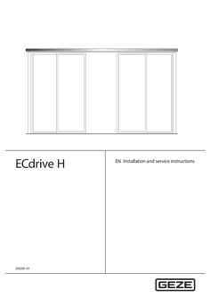
… 0159 Type Drive drawing Installation diagram Component drawing Component drawing Component drawing Name ECdrive H, drives ECdrive H ISO glass fittings Cover PL 200×40, bespoke ECdrive H Track, bespoke for ECdrive H Continuous floor guide The diagrams are subject to change without notice. Use only the most recent version.

GEZE IQ Bar 100 Series Panic & Emergency Exit Hardware 143799-02 GB Installation instructions IQ Bar 100 Series Table of Contents … 1 About this document … Product description … Key to symbols … 2 Safety and responsibility … General safety instructions . … Product liability … 3 Product overview … Technical parts list … Hardware range … 4 Fixing and installation … … .1 … .2 … .3 Introduction … IQ Bar 101/ IQ Pad 101 … IQ Bar 102/ IQ Bar 102 A/ IQ Pad 102/ IQ Bar 104 DL … Outside Access Device (OAD) … 12 OAD 100 K with Knob (cylinder cannot be removed) … 12 OAD 100 K EC with Knob and Euro Cylinder … 13 OAD 100 L EC with Lever and Euro Cylinder . … 14 … Notes on installation … 17 … Maintenance instructions … 18 … Drilling templates … 18 … Drilling Template … - to fit the operation / slave unit / OAD 100 K onto the door … 19 Drilling Template … - to fit the outside access device 100 K EC / 100 L EC onto the door … 20 IQ Bar 100 Series … About this document About this document These instructions describe the installation of the GEZE IQ Panic & Emergency Exit hardware. … Product description The GEZE IQ Panic & Emergency Exit hardware devices are designed to give instant escape, when required, by means of either a push bar or push pad on single or double doors, and can be operated from the outside of the door by an outside access device. When the outside access device is locked the door can still be released from the inside. … Key to symbols Symbols used in these instructions Important information and technical notes are emphasised to illustrate the correct operation. Symbol Meaning means “Important note” means “Additional information” XX … Symbol for a user action. Here you have to take an action. Observe the sequence if there are several action steps. Safety and responsibility The GEZE IQ Panic & Emergency Exit hardware device has been designed according to the latest technical standards and acknowledged safety rules and regulations. Dangers can, nevertheless, occur in its installation and use. You must therefore observe the following instructions. … General safety instructions àà àà àà àà àà àà Installation, commissioning and repairs must be performed only by GEZE-authorized specialists. Use only genuine GEZE parts for repairs. GEZE accepts no liability for damage arising from unauthorized modifications to the installation. Primary building safety measures must be taken by the owner. Cables must be laid according to standards VDE 0100 and VDE 0815. Doors with electrical locks along escape routes should be inspected annually by a specialist. The specialist must issue a certificate verifying the periodic inspection, which the owner must submit to the building inspectorate on request. The inspection can be performed by a GEZE service technician or a GEZE-authorized service provider. àà In addition, GEZE recommends a monthly inspection of the exit hardware device for visible damage and faults by the owner. Any identified damage or faults must be rectified immediately by a GEZE service technician or a GEZE-authorized service provider. àà In order to meet the CEN European Standards the door and frame should be of good quality and suitable to support the hardware. àà The safety features of this product are essential to its compliance with EN 179:2008 and EN 1125:2008. No modification of any kind, other than described in these instructions are permitted. Improper use Improper use includes the connection of any products that are not expressly approved by GEZE. … Product liability àà According to manufacturers liability for their products as defined in the German product liability act, the information contained herein and in the associated installation instructions and diagrams must be observed. Non-observation frees the manufacturer from their liability. àà Installation, function testing and maintenance must be performed only by GEZE-authorized personnel. GEZE accepts no liability for damage arising from unauthorized modifications to the installation. àà A combination with third-party devices invalidates GEZE’s warranty. For repair and maintenance, use only original GEZE parts. … Product overview IQ Bar 100 Series … Product overview … Technical parts list Top shoot end plug Push Bar Bottom shoot end plug … Push Pad 1. Top trip plate 2. Top shoot end plug 3. Top trip guide 4. Top shoot tube 5. Tube guide 6. Tube screws 7. Push bar main unit 8. Oval cross bar 9. Slave unit 10. Tube end plug 11. Push pad actuator 12. Push pad main unit 13. Latch keep 14. Bottom shoot tube 15. Adjustable bottom tube guide 16 Bottom shoot end plug 17 Alternative floor plate 18 Body label IQ Bar 100 Series Hardware range Single Door Sets … Point Panic Bolts IQ BAR 102 Push Bar … Point Panic Bolt with shoot bolts IQ BAR 102 A Push Bar … Point Panic Bolt with adjustable shoot bolts PAD 101 PAD 102 IQ BAR 101 Push Bar … Point Panic Latch BAR 102 A BAR 101 BAR 102 … Point Centre Panic Bolt IQ PAD 101 Push Pad … Point Panic Latch IQ PAD 102 Push Pad … Point Panic Bolt with shoot bolts IQ Bar 103 DL Push Bar … Point Double Door Set for rebated double doors BAR 102 BAR 102 BAR 102 Double Door Sets BAR 101 … Product overview IQ Bar 104 DL Push Bar … Point Double Door Set for plain meeting double doors … Fixing and installation IQ Bar 100 Series … Fixing and installation … Introduction àà These exit devices are suitable for right or left hand opening doors of up to 2440mm (8’) high x 1220mm (4’) wide. àà The door must weigh no more than 200kg and be mounted in a good quality well made frame. àà The door/doors should be checked to ensure correct hanging and freedom from binding. àà It is not recommended that the exit device is fitted to hollow core doors. àà The exit devices are not intended for use on double action (double swing) doors. àà Ensure that no weather strips or fixings on the door or door frame stop the device from working properly. àà If the door is to be fitted with a device which allows you to open it from outside, read the instructions provided with that device. àà All measurements are in millimetres. àà For installation of double door sets refer to the instuctions of the relevant single door units. àà IQ Bar 103 V DL àà IQ Bar 104 V DL … = IQ Bar 101 = IQ Bar 102 + IQ Bar 102 + IQ Bar 102 IQ Bar 100 Series … Fixing and installation IQ Bar 101/ IQ Pad 101 These units can be fitted on a single door. IQ Bar 101 can also be fitted on the first opening (active) leaf of the IQ Bar 103 DL double doors set. In this case a revised fitting position for the unit is however required as shown on these installation instructions. In case of using an outside access device (OAD) fit the OAD first before continuing with the installation of the panic device. Step A: Re-handing the panic latch (if required) Supplied as standard the push bar/pad panic latch is assembled to suit right hand opening doors. To reverse the assembly to suit left hand opening doors proceed as follows. XX 1. Remove the panic latch backplate followed by the drive casting and actuating pressing. XX 2. The latch bolt/blanking casting assembly is reversible in the body by compressing between forefinger and thumb and replacing in the required position. XX 3. Reverse the position of the actuating pressing on the drive casting. Refit in the latch body ensuring that the drive casting pivot is correctly located and that the drive casting spigot is fully engaged with the latch bolt pressing. XX … . Refit the backplate and test for correct operation. Step B: Fitting the main/operating unit XX Determine the height of the push bar/pad (A) between 900mm and 1100mm from floor level. Mark this position on the jamb adjacent to the door. XX Establish the mounting position for the panic latch operating unit 10mm from the jamb. Place the template on the door and align the push bar/pad height and the rebate line with the jamb and drill the fixing holes required. Remove the template and fix the operating unit. XX For double doors establish the mounting position for the panic latch operating unit 10mm from the edge of the second door. Position the panic bolt operating unit on the last opening door 35mm from the panic latch operating body and fix. A Push Bar / Push Pad centre height: between 900mm & 1100mm B Push Bar length = B - 8mm Re-handing the panic / emergency exit latch … 1 … Standard latch keep P1601 Step C: Fitting the Keep XX For a single door fit the keep plate to the jamb. Note that only the keep face within the jamb rebate should be recessed to provide flush fitting. XX For double doors fit the box keep 300 to the adjacent (second opening) door. Note the position of the panic bolt unit for this application. … Fixing and installation XX Operate the panic latch and ensure that the latch bolt moves and returns freely, enters the keep fully and allows the door to be opened easily and closed securely. IQ Bar 100 Series Fixing the push bar Step D: Fitting the slave unit & push bar IQ Bar only XX Using the template position the slave unit on the door directly opposite the operating unit and 10mm from the jamb and fix. XX Measure the outside dimension (B) across the operating arms. Subtract 8mm and cut the plain end of the push bar to length. Drill a 10mm dia. hole in the plain end of the push bar on the centre line and 12mm from the end. XX Locate the push bar in the operating arms and ensure that the holes align with the arm clamp screws. Insert the end plugs into both ends of the push bar flush with the operating arms and fully tighten both screws. Step E: Testing the operation XX Test the unit to ensure that when the Push Bar/ Pad is operated the door opens immediately and swings freely. When closed the centre latch engages fully in the keep and holds the door securely shut. Step F: Fitting the name plate and the sign XX Remove backing paper and fit self adhesive body label into the recessed location on the body casting to cover top fixing screws. For push bar: Fit the self adhesive “Push Bar to Open” sign onto the door immediately above the push bar For push pad: Fit the self adhesive “Push Pad to Open” sign onto the door by the push pad. Centre latch keep double door (300) … IQ Bar 100 Series … Fixing and installation IQ Bar 102/ IQ Bar 102 A/ IQ Pad 102/ IQ Bar 104 DL These units can be fitted on a single door or in one of the following double door sets: àà Set IQ Bar 104 DL with IQ Bar 102 fitted on both leafs of non rebated double doors. àà Set IQ Bar 103 DL with IQ Bar 102 fitted on the last opening (inactive) leaf of double rebated doors together with IQ Bar 101 on the first opening (active) leaf. In this case a revised fitting position for this unit is however required, which is shown on the other unit’s installation instructions. In case of using an outside access device (OAD) fit the OAD first before continuing with the installation of the panic device. Step A: Fitting the main/operating unit XX Determine the height of the push bar/pad (A) between 900mm and 1100mm from floor level. Mark this position on the jamb adjacent to the door. XX Establish the mounting position for the panic bolt operating unit 10mm from the jamb. Place the template on the door and align the push bar/pad height and the rebate line with the jamb and drill the fixing holes required. Remove the template and temporarily fix the operating unit. XX For Non-Rebated double doors establish the mounting position for the panic bolt operating unit 10mm from the edge of its door leaf. Repeat the process on the second door. A Push Bar / Push Pad centre height: between 900mm & 1100mm B Push Bar length = B - 8mm Step B: Preparing the shoot tubes XX Refer to the diagram on page 10. Follow the correct procedure for your product: For IQ Bar 102 (standard shoot bolts) XX Accurately Measure the Bottom (short) length dimension (C1). XX When using the easy clean socket (G) or the alternative floor plate (not shown) subtract 8mm from length C1 and cut the plain end of the tube to this length. XX When using the surface mounted bottom keep 3405 (supplied separately) subtract 23mm from length C1 and cut the plain end of the tube to this length. XX Drive the bottom (short) shoot end plug No.P0601 into the cut end. XX The plug must be driven in fully against the tube end. XX Accurately Measure the Top (long) length dimension (C2). XX When using the Top trip plate P0401 (as supplied) subtract 54mm from length C2 and cut the plain end of the tube to this length. … Fixing and installation XX XX XX When Using the Surface mounted top keep 3405A (supplied separately) subtract 69mm from length C2 and cut the plain end of the tube to this length. Drive the top (long) shoot end plug No. P0501 into the cut end. The plug must be driven in fully against the tube end. For IQ Bar 102 A (adjustable shoot bolts) XX Accurately Measure the Bottom (short) length dimension (C1). XX When using the easy clean socket (G) or the alternative floor plate (not shown) subtract 66mm from length C1 and cut the plain end of the tube to this length. XX When using the surface mounted bottom keep 3405 (supplied separately) subtract 81mm from length C1 and cut the plain end of the tube to this length. XX Drive threaded shoot bush No. P0164 into the cut end. The Bush must be driven in fully against the tube end. XX Screw bottom (plain) shoot end No. P0162 into the shoot bush leaving a 4mm gap. XX Accurately Measure the Top (long) length dimension (C2). XX When using the Top trip plate P0401 (as supplied) subtract 61mm from length C2 and cut the plain end of the tube to this length. XX When Using the Surface mounted top keep 3405 (supplied separately) subtract 76mm from length C2 and cut the plain end of the tube to this length. XX Drive threaded shoot bush No. P0164 into the cut end. The Bush must be driven in fully against the tube end. XX Screw the top (grooved) shoot end No. P0159 into the shoot bush leaving a 4mm gap. Step C: Fitting the shoot tubes and guides XX Remove the panic bolt operating unit from the door and fit top & bottom shoot tube assemblies to the panic bolt unit spigots and retain with socket head screws positioned adjacent to the door face. XX Position shoot guides No. P0201 on the shoot tubes (for IQ 102 A use guide No. P0206 for the bottom tube). Refit panic bolt unit and fit guides to the door using the round head screws. Shoots must be vertical and panic bolt unit and guides must be in alignment. XX Keeping the operating arm fully depressed locate the top trip assembly No. P1201 on the top shoot end. Use a 3mm thick spacer between the end of the top shoot and the underside of the head frame to ensure that the shoot is fully withdrawn and secure the top trip guide assembly to the door. 10 IQ Bar 100 Series Adjustable bolt with GAP L C1 C2 D E F G H I J K L Bottom shoot tube length Top shoot tube length Top trip plate Tube Guides Socket head screws Easy clean floor socket No. P0301 Main/operating unit Slave unit Top Trip Guide Assembly Bottom Tube guide (P0201 Non-adjustable bolts / P0206 Adjustable bolts) 55mm (Adjustable Bolts & standard keep) 70mm (Adjustable Bolts & surface mounted keep) 44mm (None-adjustable Bolts & standard keep) 59mm (Non-adjustable Bolts & surface mounted keep) Fixing the push bar IQ Bar 100 Series Step D: Fitting the keeps XX The Top Trip Keep Plate P0401 should be fitted flush in the head frame and with its narrow edge level with the frame rebate. Use the short c´sk. head screws provided. XX Easy clean floor socket No. P0301 for solid floors should be fitted flush with the finished floor surface and with its edge level with the inside door face. Alternative floor plate No. P1301 for wooden floors must be fitted flush with the finished floor surface and with its narrow edge level with the door face. XX Operate the panic bolt and ensure that the top trip device holds both shoots in the fully withdrawn position when the door is open. XX Close the door and ensure that the top trip releases the shoots to engage fully in both top and bottom keeps and holds the door firmly closed in its rebate. Step E: Fitting the slave unit & push bar IQ Bar only XX Using the template position the slave unit on the door directly opposite the operating unit and 10mm from the jamb and fix. XX Measure the outside dimension (B) across the operating arms. Subtract 8mm and cut the plain end of the push bar to length. Drill a 10mm dia. hole in the plain end of the push bar on the centre line and 12mm from the end. XX Locate the push bar in the operating arms and ensure that the holes align with the arm clamp screws. Insert the end plugs into both ends of the push bar flush with the operating arms and fully tighten both screws. Fixing and installation Top Trip Keep Plate P0401 Surface mounted bottom bolt keep 3405 surface mounted top trip keep 3405A Step F: Testing the operation XX Test the unit to ensure that when the Push Bar/ Pad is operated the door opens immediately and swings freely. When closed the bolts engage fully in the keeps and holds the door securely shut. Step G: Fitting the name plate and the sign XX Remove backing paper and fit self adhesive body label into the recessed location on the body casting to cover top fixing screws. For push bar: Fit the self adhesive “Push Bar to Open” sign onto the door immediately above the push bar For push pad: Fit the self adhesive “Push Pad to Open” sign onto the door by the push pad. 11 Fixing and installation Outside Access Device 100 K 58 mm The outside access device provides a lockable entry facility for doors fitted with IQ 100 Series. The outside access device always allows immediate exit regardless of whether device is locked or unlocked. For double door installations with rebated meeting door styles, the outside access device must be fitted on the first opening (last closing) door leaf. XX XX XX XX XX 12 Working on the inside face of the door use the template to establish the fixing position for Panic Bolt or Panic latch as described in the appropriate instruction page. In addition using the template mark and drill the drive spindle hole 14mm dia. and two outside access device mounting holes 7mm through and counterbore 14mm dia. x 6mm deep. Trial fit the c‘sk. head mounting screws/ washers and measure the projection on the outside of the door. Adjust the depth of the counterbore to provide 19mm screw projection. If projection exceeds 19mm cut the screw to length. Locate the drive spindle into the square hole in the outside access device. Pass the spindle through the door and fix the body securely. Ensure that the body is square to the edge of the door and that the drive spindle is centred in the hole and that it rotates freely. Ensure that the drive spindle is fully engaged on the outside access device. Cut the spindle so that 13mm projects from the door face. A minimum of 10mm is required for correct operation. Engage the drive spindle with the square hole in the panic bolt/panic latch and install following the appropriate fitting procedure instruction page. Test the operation of the outside access device. To open the door hold the knob to prevent it turning. Insert the key and turn it anti-clockwise one complete revolution (the key can then be removed if required). Rotate the knob until a slight click is felt. Continue to turn the knob approximately ¼ turn to operate the panic bolt/panic latch. To disengage the outside access device hold the knob and turn the key clockwise one revolution and remove. Check for free and correct operation of the outside access device and the panic bolt/panic latch. 100 mm 18 mm 19 mm 13 mm Ø 14 mm XX 71 mm OAD 100 K with Knob (cylinder cannot be removed) 50 mm … .1 18 mm 23 mm Outside Access Device (OAD) … mm 14 mm … IQ Bar 100 Series Dim. A. Push Bar Height IQ Bar 100 Series … .2 OAD 100 K EC with Knob and Euro Cylinder Fixing and installation Outside Access Device 100 K EC 60 mm Step A: Fitting procedure XX XX XX 37 mm 69 mm 93 mm 30 mm 13 mm Ø 14 mm XX 109 mm XX 178 mm XX Working on the inside face of the door use the template to establish the fixing position for Panic Bolt or Panic latch as described in the appropriate instruction page. In addition using the template mark and drill the drive spindle hole 14mm dia. and three outside access device mounting holes 7mm through. Recess the inside face of the door 5mm deep to allow the mounting plate to be fitted. Trial fit the c’sk. head mounting screws and measure the projection on the outside of the door. Cut the screws to provide 30mm maximum projection. Locate the drive spindle into the sguare hole in the outside access device. Pass the spindle through the door and fix the body securely. Ensure that the body is square to the edge of the door and that the drive spindle is centred in the hole and that it rotates freely. Ensure that the drive spindle is fully engaged in the outside access device. Cut the spindle so that 13mm projects from the door face. A minimum of 10mm is required for correct operation. Engage the drive spindle with the square hole in the panic bolt/panic latch and install following the appropriate fitting procedure instruction page. Test the operation of the outside access device. To open the door insert the key and turn it anticlockwise one complete revolution (the key can then be removed if required). Rotate the knob until it engages and continue to turn approximately 1/4 turn to operate the panic bolt/panic latch. To disengage the outside access device turn the key clockwise one revolution and remove. Check for free and correct operation of the outside access device and the panic bolt/panic latch. 36 mm … mm XX Step B: Cylinder preparation This 100 K EC master keying outside access device is normally supplied complete with cylinder lock but for specific applications will accept most 40mm Euro profile cylinders if required. To suit master keying situations the outside access device can be supplied with pre-formed aperture to suit Euro profile cylinder fitting. The cylinder selected should be drilled and tapped M5 as shown. 19,5 mm Step C: Cylinderfitting Place the cylinder into the shaped body aperture and fix securely through the backplate with the c’sk head M5 screw supplied. Dim. A. Push Bar Height Drill and Tap M5 12 mm 13 Fixing and installation … .3 OAD 100 L EC with Lever and Euro Cylinder IQ Bar 100 Series Diagram … Notes on operation Rotate the key anti-clockwise to unlock the device. Rotate the key clockwise to lock the device. In both cases rotate the key until it stops (‚mechanism clicks‘) then counter-rotate to return to the neutral position to remove the key, do not try to continue rotating the key. When locked the operation of the lever is blocked. When unlocked the lever will move freely and operate the panic / emergency exit device installed on the inside of the door. To protect the device against excessive force a shear screw is used to secure the lever. Step A: Device preparation Lever handing XX Attach the lever to the shank in the correct orientation to suit the door handing (see diagram 1). XX Secure to the device with the supplied shear screw. Use the hex key provided. Do not over tighten. Diagram … Setting the drive spindle handing The drive spindle must be set to suit the required handing / type of exit device. Refer to the diagram … to determine the required position. Follow the procedure below to set the handing. XX Ensure device is unlocked. Fully operate the lever & hold in position. The drive spindle will rotate. XX Using one of the square spindles (in screw pack) Continue to turn the drive spindle (in the direction of rotation) towards the required position until it stops. XX Return the lever to the start position. XX Continue to rotate the drive spindle until the mark on the drive spindle lines up with the appropriate mark in the backplate. The drive spindle is now handed. Installation / replacement of cylinder XX Remove the … cylinder bracket screws as shown in diagram 3. Withdraw the cylinder bracket from the unit. XX Change / install the cylinder. Secure cylinder to bracket with the M5 x 20 cylinder screw provided. XX Replace the bracket / cylinder assembly. Re-secure with the cylinder bracket screws. 14 B / L LH position To suit IQ Bar/Pad 102 regardless of door handing and IQ Bar/Pad 101 used on left hand doors L RH position To suit IQ Bar/Pad 101 used on right hand doors Diagram … IQ Bar 100 Series Fixing and installation Step B: Device installation Establish unit position Working on the inside face of the door. Use the template to establish the fixing position of the panic / emergency exit device. Follow the instructions on the template. Determine height 900mm to 1100mm from floor. Align template correctly with the edge of frame (for single door) or the edge of 2nd opening door (for double doors). For existing installations where access device is to be retrofitted remove the exit device and align template with the existing exit device fixing holes. Door preparation XX Pilot the exit device fixing holes. Drill ø16mm spindle hole through the door. XX For timber doors: drill through … off clearance holes for access device fixings. For improved strength the mortice mounting plate can be used. The plate must be mortised flush into door face. XX For steel doors: drill through … off clearance holes for access device fixings. Countersink these holes directly on the inside face of the door. Preparing the fixing screws XX Trial fit the … off M5 x 70 fixing screws. Cut the screws to provide a maximum projection of 15mm from the outside face of the door. Select & prepare spindle XX Select the correct type of spindle to suit the panic / emergency exit device being used. For latch type fit the spindle adaptor (see diagrams). Ensure it is fully inserted into the square drive of the panic / emergency exit latch unit. XX Fit the access device using the previously prepared screws. XX Insert the correct drive spindle through the door and locate into the square drive / adaptor in the access device. XX Mark 13mm projection from the inside door face. Note: when using the mortice mounting plate measure from the face of the door not the plate. XX Cut the spindle to length. De-burr the cut end. Note: cut the square end when using the latch spindle. Plain square (bolt) spindle for shoot bolt versions Reduced end (latch) spindle for latch versions only Install the exit device XX Continue to install the exit device follow the instructions (on the appropriate pages) for that device. Check / test installation XX Test the operation of the finished installation. Check for free and correct operation of both the outside access device and the panic / emergency exit hardware. 15 Replacing the shear screw XX Carefully unscrew the broken shear pin head. Note: use square ended (none ball end) 3mm hex key. XX Pull the lever off to remove (avoid rotating). XX Clear the remaining shear screw from the shank. Note: push out from the none sheared side. XX Inspect the shank & lever for damage. Remove any burrs to allow the lever to re-fit. Note: replacement levers are available. XX Re-fit lever with a new shear screw. 16 Outside Access Device 100 L EC … Notes on installation As part of the requirements of EN1125: 2008 (Panic Exit devices) / EN179: 2008 (Emergency Exit devices) we must provide you with the following additional information. The safety features of this product are essential to its compliance with EN179 / EN1125: 2008. No modifications of any kind, other than described in these instructions are permitted. (Some of the information below may be duplicated in this Installation instructions). àà All devices are suitable for use on double / single doors up to 2440mm x 1220mm, door mass up to 200kg. àà Before fitting an exit device to a door, the door should be checked to ensure correct hanging and freedom from binding. A maximum of 5mm door distortion is allowed. We do not recommend that any of our exit devices be fitted to hollow core doors. It is recommended to verify that the door construction allows the use of the device, i.e. verify that: àà Offset hinges and engaging leaves allow both leaves to be opened simultaneously. àà The gap between door leaves does not differ from that which is specified in the main installation instructions (if stated). àà The operating elements do not interfere. NOTE: Panic / Emergency exit devices manufactured in accordance with EN1125 & EN179 will provide a high degree of safety and reasonable security provided that they are fitted to doors and door frames that are in good condition. àà Before fitting a Panic / Emergency exit device to a fire / smoke resisting door, the fire certification of the fire door assembly on which the exit device has been tested (to prove suitability for use on fire doors) should be examined. It is of utmost importance that an exit device is not used on a fire door assembly of a greater fire resistance time than it is approved for. àà Care should be taken to ensure that any seals or weather-stripping fitted to the complete door assembly, does not inhibit the correct operations of the Panic / Emergency exit device. àà On double door sets with rebated meeting stiles and where both leaves are fitted with Panic / Emergency exit devices, it is essential to check that either leaf will open when its exit device is activated and also that both leaves will open freely when both exit devices are operated simultaneously. àà These Panic / Emergency exit devices are manufacture in one size. àà Category … (standard projection) Panic / Emergency exit devices should be used in situations where there is restricted width for escape, or where the doors to be fitted with the Panic / Emergency exit devices are not able to open beyond 90°. àà Where an exit device is to be fitted to a glazed door, it is essential that the glazing is tempered or laminated glass. àà Different fixings are available for fitting Panic / Emergency exit devices to metal doors, etc. Timber fixings are supplied as standard. Note: Exit devices suffixed ‘SD’ (101 SD) include steel door fixings as standard. àà None of our Panic / Emergency exit devices are intended for use on double action (double swing) doors. àà The fixing instructions should be carefully followed during installation. These instructions should be passed on by the installer to the user. àà The horizontal bar (EN1125 devices) / operating element (EN179 devices) should normally be installed at a height of between 900 mm and 1100 mm from the finished floor level, when the door is in the secured position. Where it is known that the majority of the occupants of the premises will be young children, consideration should be given to reducing the height of the bar / operating element accordingly. àà The horizontal bar should be installed so as to provide the maximum effective length (EN1125 devices) àà When installing (EN179) lever operated Emergency exit devices, particularly on doors with raised or recessed surfaces, consideration should be given to minimizing any potential safety risks, such as the trapping of fingers or clothing. àà The bolt heads / latches and keepers should be fitted to provide secure engagement. Care should be taken to ensure that no projection of the bolt heads / latches, when in the withdrawn position, can prevent the door swinging freely. àà Where exit devices are to be fitted to double doorsets with rebated meeting stiles and self closing devices, a door coordinator device in accordance with EN 1158 should be fitted to ensure the correct closing sequence of the doors. This recommendation is particularly important with regard to fire/smoke resisting door assemblies. àà No additional devices for securing the door in the closed position should be fitted. This does not preclude the installation of self closing devices. àà If a door closing device is to be used to return the door to the closed position, care should be taken not to impair the use of the doorway by the young, elderly and infirm. àà Any keepers or protection plates provided should be fitted in order to ensure compliance with EN1125 / EN179. àà EN1125 Panic exit devices: the provided sign which reads; “Push bar to open” should be affixed on the inside face of the door immediately above the horizontal bar. àà EN179 Emergency exit devices: the provided sign which reads; “Push Pad to open” should be affixed on the inside face of the door immediately above the Push Pad operating element. 17 … Maintenance instructions It is important that all a panic and emergency exit hardware devices are inspected and maintained properly to ensure safety is maintained when exiting a building in any situation. Once the device is fitted regular maintenance is recommended. Weekly: XX Make sure the Exit Device functions correctly. XX Any fixings that have worked loose should be re-secured XX Any damaged components should be replaced. XX Ensure there are no obstructions which prevent the panic unit from functioning correctly. Every three months: XX Check for wear, any visible worn components should be replaced. The following is the routine maintenance procedure as recommended by EN1125 / EN179:XX Inspect and operate the exit device to ensure that all components are in a satisfactory working condition. If possible using a force gauge, measure and record the operating forces to release the exit device. XX Ensure the keeper(s) is (are) free from obstruction. XX Check that the exit device is lubricated in accordance with the producer’s instructions. XX Check that no additional locking devices have been added to the door since its original installation. XX Check periodically that all components of the system are still correct in accordance with the list of approved components originally supplied with the system. XX Check periodically that the operating element is correctly tightened and, If possible using a force gauge, measure the operating forces to release the exit device. Check that the operating forces have not changed significantly from the operating forces recorded when originally installed. … Drilling templates Overview àà Drilling Template … - to fit the operation / slave unit / OAD 100 K onto the door àà Drilling Template … - to fit the outside access device OAD 100 K EC / 100 L EC 18 … EDGE OF DOOR (SINGLE DOOR) / EDGE OF 2ND OPENING DOOR (DOUBLE DOORS) Drilling Template … - to fit the operation / slave unit / OAD 100 K onto the door NOTE:3 HOLES ONLY REQUIRED FOR 100 K OUTSIDE ACCESS DEVICE. … HOLES CSK INSIDE DOOR FACE. EDGE OF DOOR (SINGLE DOOR) / EDGE OF 2ND OPENING DOOR (DOUBLE DOORS) 10mm 10mm 1000mm ± 100mm FROM FLOOR 19 20 EDGE OF DOOR (SINGLE DOOR) / EDGE OF 2ND OPENING DOOR (DOUBLE DOORS) … Drilling Template … - to fit the outside access device 100 K EC / 100 L EC onto the door NOTE:HOLES & RECESS ONLY REQUIRED FOR OUTSIDE ACCESS DEVICE. 1000mm ± 100mm FROM FLOOR EDGE OF DOOR (SINGLE DOOR) / EDGE OF 2ND OPENING DOOR (DOUBLE DOORS) 10mm 10mm LISTED ACCESSORIES Only the accessories listed below can be used with this product range. The use of any other accessory may invalidate the relevant products EN1125 / EN179 CE certification. PRODUCT No. DESCRIPTION COMPATIBILITY 3404 OUTSIDE ACCESS DEVICES Knob operated Outside Access Device Knob operated Outside Access Device with Euro cylinder Knob operated Outside Access Device with Oval aperture (cylinder not supplied) KEEPS Standard Latch Keep – Steel Door (Similar to P1601) 3405 Surface mounted Bottom bolt Keep 3405A Surface mounted Top Trip Keep 300 ED150 Double door latch keep (As Supplied with: IQ Bar 103 DL) Single & Double Door Latch Keep –Surface Mounted. P0401 Standard Top Trip Plate P1301 Standard Floor Plate bolt keep. P1601 Standard Latch Keep – Timber Door (Similar to 3404) 100K 100 K EC 100 L EC (Replaces 3404 / P1601 on single doors. Replaces 300 on double doors.) Use with all GEZE IQ Bar 100 series range for use with IQ Bar 101, IQ Pad 101 on steel doors IQ Pad 102, IQ Bar 102, IQ Bar 104 DL, IQ Bar 103 DL IQ Pad 102, IQ Bar 102, IQ Bar 104 DL, IQ Bar 103 DL IQ Bar 101, IQ Pad 101 IQ Bar 101, IQ Pad 101 IQ Pad 102, IQ Bar 102, IQ Bar 103 DL, IQ Bar 104 DL IQ Pad 102, IQ Bar 102, IQ Bar 103 DL, IQ Bar 104 DL IQ Bar 101, IQ Pad 101 Unless other wise stated compatibility is assumed with all the various suffixed variations (e.g. ‘A’, ‘SD’, ‘MS’) of the basic product. CE MARKING All devices are intended for use on single / double outward opening route escape doors, fire / none-fire rated dependant on device (see below). Where fire rated; devices are certified for use on the following door assemblies for the stated times: 60 minutes on Timber door assemblies (doorsets to EN 1634-1 Codes: TT, ITT and ITC). 240 minutes on Steel door assemblies (doorsets to EN 1634-1 Codes: IMM, and MM). Minimum resistance for all devices: a maximum pulling force of 1000N was achieved against the fixings under the abuse test. Below is the CE marking information for the entire range. Applicable products are clearly listed below their relevant markings. 1121 EN 1125: 2008 PANIC EXIT DEVICES … 7 … B … 3 … 2 A A AAA041 11 1121 EN 179: 2008 PANIC EXIT DEVICES … 7 … B … 3 … 2 B A ABB048 11 Category … Projection. Category … Projection. Field of Door application: Category A (Single & Double) Field of Door application: Category A (Single & Double) Suitable for use on fire / smoke doors. Suitable for use on fire / smoke doors. Applicable to Products: IQ Bar 102, IQ Bar 102A, IQ Bar 101, IQ Bar 104 DL, IQ Bar 103 DL Applicable to Products: IQ Pad 102, IQ Pad 101 GEZE GmbH, Reinhold-Vöster-Str. 21-29, D-71229 Leonberg 21 Notes: 22 Notes: 23 Germany GEZE GmbH Niederlassung Süd-West Tel. +49 (0) 7152 203 594 E-Mail: leonberg.de@geze.com GEZE GmbH Niederlassung Süd-Ost Tel. +49 (0) 7152 203 6440 E-Mail: muenchen.de@geze.com GEZE GmbH Niederlassung Ost Tel. +49 (0) 7152 203 6840 E-Mail: berlin.de@geze.com GEZE GmbH Niederlassung Mitte/Luxemburg Tel. +49 (0) 7152 203 6888 E-Mail: frankfurt.de@geze.com GEZE GmbH Niederlassung West Tel. +49 (0) 7152 203 6770 E-Mail: duesseldorf.de@geze.com GEZE GmbH Niederlassung Nord Tel. +49 (0) 7152 203 6600 E-Mail: hamburg.de@geze.com GEZE Service GmbH Tel. +49 (0) 1802 923392 E-Mail: service-info.de@geze.com Austria GEZE Austria E-Mail: austria.at@geze.com www.geze.at Hungary GEZE Hungary Kft. E-Mail: office-hungary@geze.com www.geze.hu Scandinavia – Sweden GEZE Scandinavia AB E-Mail: sverige.se@geze.com www.geze.se Baltic States – Lithuania / Latvia / Estonia E-Mail: baltic-states@geze.com Iberia GEZE Iberia S.R.L. E-Mail: info.es@geze.com www.geze.es Scandinavia – Norway GEZE Scandinavia AB avd. Norge E-Mail: norge.se@geze.com www.geze.no Benelux GEZE Benelux B.V. E-Mail: benelux.nl@geze.com www.geze.be www.geze.nl India GEZE India Private Ltd. E-Mail: office-india@geze.com www.geze.in Scandinavia – Denmark GEZE Danmark E-Mail: danmark.se@geze.com www.geze.dk Bulgaria GEZE Bulgaria - Trade E-Mail: office-bulgaria@geze.com www.geze.bg Italy GEZE Italia S.r.l E-Mail: italia.it@geze.com www.geze.it Singapore GEZE (Asia Pacific) Pte, Ltd. E-Mail: gezesea@geze.com.sg www.geze.com China GEZE Industries (Tianjin) Co., Ltd. E-Mail: chinasales@geze.com.cn www.geze.com.cn GEZE Engineering Roma S.r.l E-Mail: italia.it@geze.com www.geze.it South Africa GEZE South Africa (Pty) Ltd. E-Mail: info@gezesa.co.za www.geze.co.za GEZE Industries (Tianjin) Co., Ltd. Branch Office Shanghai E-Mail: chinasales@geze.com.cn www.geze.com.cn GEZE Industries (Tianjin) Co., Ltd. Branch Office Guangzhou E-Mail: chinasales@geze.com.cn www.geze.com.cn GEZE Industries (Tianjin) Co., Ltd. Branch Office Beijing E-Mail: chinasales@geze.com.cn www.geze.com.cn France GEZE France S.A.R.L. E-Mail: france.fr@geze.com www.geze.fr Korea GEZE Korea Ltd. E-Mail: info.kr@geze.com www.geze.com Poland GEZE Polska Sp.z o.o. E-Mail: geze.pl@geze.com www.geze.pl Romania GEZE Romania S.R.L. E-Mail: office-romania@geze.com www.geze.ro Russia OOO GEZE RUS E-Mail: office-russia@geze.com www.geze.ru Switzerland GEZE Schweiz AG E-Mail: schweiz.ch@geze.com www.geze.ch Turkey GEZE Kapı ve Pencere Sistemleri E-Mail: office-turkey@geze.com www.geze.com Ukraine LLC GEZE Ukraine E-Mail: office-ukraine@geze.com www.geze.ua United Arab Emirates/GCC GEZE Middle East E-Mail: gezeme@geze.com www.geze.ae United Kingdom GEZE UK Ltd. E-Mail: info.uk@geze.com www.geze.com GEZE GmbH Reinhold-Vöster-Straße 21–29 71229 Leonberg Germany Tel.: 0049 7152 203 … Fax.: 0049 7152 203 310 www.geze.com
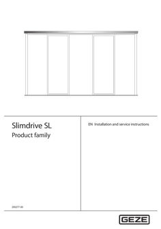
… 0159 Assembly group drawing Floor guide continuous 70715-9-9818 Installation drawing Continuous floor guide SL + SLT 70715-9-9835 Installation drawing Insulated glass leaf SL 70717-9-0967 Installation drawing Side panel SL/SLT The diagrams are subject to change without notice. Use only the most recent version.

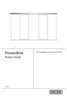
… 0159 Assembly group drawing Continuous floor guide 70506-2-0240 Component drawing Cover version 200×90×6500 70506-2-0238 Component drawing Cover version 150×90×6500 70506-2-0218 Component drawing Cover, bespoke 200×105/90 70506-2-0217 Component drawing Cover, bespoke 150×105/90 70499-2-0247 Component drawing Track, perforated 70485-2-0200 Component drawing Track, bespoke PL 2-leaf 70485-2-0251 Component drawing Track, bespoke PL 1-leaf 70715-9-9872 Installation drawing ISO leaf lock M aluminium secondary closing edge 70715-9-9873 Installation drawing ISO leaf lock M rubber secondary closing edge 70715-9-9874 Installation drawing ISO leaf lock M aluminium secondary closing edge if fixed panel installed under track 70709-9-0994 Installation drawing Toughened safety glass leaf 70715-9-9850 sheet
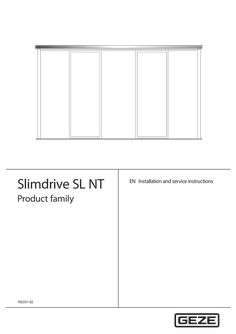
… 0159 Assembly group drawing Continuous floor guide 70715-9-9854 Installation drawing ISO leaf Slimdrive SL NT 70715-9-9864 Installation drawing ISO leaf, rubber secondary closing edge, Lock M, Slimdrive SL NT 70715-9-9863 Installation drawing ISO leaf, rubber secondary closing edge, Lock A, Slimdrive SL NT The diagrams are subject to change without notice. Use only the most recent version.
… 0159 Installation diagram Installation diagram Installation diagram Installation diagram Installation diagram Installation diagram Installation diagram Installation diagram Installation diagram Installation diagram Installation diagram Installation diagram Installation diagram Component drawing Component drawing Assembly group drawing Name ECdrive T2, drives ISO (toughened safety glass) glass fitting, 1-leaf ISO (toughened safety glass) glass fitting, 2-leaf ESG (toughened safety glass) glass fitting, 1-leaf ESG (toughened safety glass) glass fitting, 2-leaf ISO (toughened safety glass) post-rail construction 1-leaf ISO (toughened safety glass) post-rail construction 2-leaf ESG (toughened safety glass) post-rail construction 1-leaf ESG (toughened safety glass) post-rail construction 2-leaf ISO Lock A 1-leaf ISO Lock A 2-leaf ISO Lock M 1-leaf ISO Lock M 2-leaf ISO post-rail construction Lock A 1-leaf ISO post-rail construction Lock A 2-leaf ISO post-rail construction Lock M 1-leaf ISO post-rail construction Lock M 2-leaf Protective leaf attachment ISO-ESG (toughened safety glass) side panel on site Wooden leaf on site 1-leaf Wooden leaf on site 2-leaf Safety leaf for sliding door drives Cover 100×132 Cover 150×132 Continuous floor guide The diagrams are subject to change without notice. Use only the most recent version.