Search filter
99 results found
Wiring Diagram FT4 A
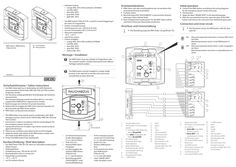
… Wiring diagram àà The RWA button FT4A/24 V DC is used for manual triggering in the event of a hazard (fire). àà Surface-mounted housing àà Switching power max. 100 mA at 24 V DC àà Current consumption LED … The RWA button must be installed in a clearly visible position in the stairwell or corridor and must not be concealed by an open door leaf. àà Der RWA-Taster darf nur in Verbindung mit GEZE-Notstromsteuerzentralen E 260 N (VdS), MBZ 300, THZ und THZ Comfort eingesetzt werden. àà Der Anschluss erfolgt gemäß dem Anschlussplan der Notstromsteuerzentrale. àà Die Leitungsverlegung und der Anschluss darf nur von einer zugelassenen Elektrofirma vorgenommen werden. XX Bestimmungen der örtlichen Feuerwehr beachten. XX Klebeschild mit Angabe der RWA-Taster-Nummer bauseits auf die Innenseite des RWA-Tasters kleben. XX RWA-Taster vor Bauschmutz schützen. àà The RWA button may only be used in combination with GEZE emergency power control units E 260 N (VdS), MBZ 300, THZ and THZ Comfort. àà Connection is made in accordance with the wiring diagram for the emergency power control unit. àà Laying and connection of cables may only be carried out by an approved electrician. XX Observe any conditions prescribed by the local fire brigade. XX Apply the sticker with details of the RWA button number onto the inside of the RWA button on site. XX Protect the RWA button from building dirt. Überwachungswiderstände aktiv, im letzten RWA-Taster der Reihe Monitoring resistors not active, in all predecessors in series Der RWA-Taster muss gut sichtbar im Treppenhaus oder Flur montiert werden und darf nicht durch einen offenen Türflügel verdeckt werden. Sicherheitshinweise / Safety instructions The illustration shows the RWA button with the door opened. ON Montage / Installation 162458-01 Connect the RWA button according to the wiring diagrams for the emergency power control unit used. Test function. Apply the label "SMOKE VENT" in the desired language. After the successful function test, open the door of the RWA button and remove the card cover from behind the glass pane.
(PDF | 1 MB)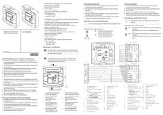
Wiring diagram FT
… Wiring diagram àà àà àà àà àà àà àà Stromaufnahme Signalgeber max. 2,5 mA bei 24 V Signallautstärke ca. 60 dB(A) Glasscheibe auswechselbar –10 °C ...+55 °C nur für trockene Räume max. … 7 Montage / Installation Der RWA-Taster muss gut sichtbar im Treppenhaus oder Flur montiert werden und darf nicht durch einen offenen Türflügel verdeckt werden. 195730-00 Connect the RWA button according to the wiring diagrams for the emergency power control unit used. Set DIP switches S3 and S4 according to the required function. Test function. Apply the label "SMOKE VENT" in the desired language. After the successful function test, open the door of the RWA button and remove the card cover from behind the glass pane. … The RWA button must be installed in a clearly visible position in the stairwell or corridor and must not be concealed by an open door leaf. Sicherheitshinweise / Safety instructions àà Der RWA-Taster darf nur in Verbindung mit GEZE-Notstromsteuerzentralen E 260 N (VdS), MBZ 300, THZ und THZ Comfort eingesetzt werden. àà Der Anschluss erfolgt gemäß dem Anschlussplan der Notstromsteuerzentrale. àà Die Leitungsverlegung und der Anschluss darf nur von einer zugelassenen Elektrofirma vorgenommen werden. XX Bestimmungen der örtlichen Feuerwehr beachten. XX Klebeschild mit Angabe der RWA-Taster-Nummer bauseits auf die Innenseite des RWA-Tasters kleben. XX RWA-Taster vor Bauschmutz schützen. àà The RWA button may only be used in combination with GEZE emergency power control units E 260 N (VdS), MBZ 300, THZ and THZ Comfort. àà Connection is made in accordance with the wiring diagram for the emergency power control unit. àà Laying and connection of cables may only be carried out by an approved electrician. XX Observe any conditions prescribed by the local fire brigade. XX Apply the sticker with details of the RWA button number onto the inside of the RWA button on site. XX Protect the RWA button from building dirt. Kurzbeschreibung / Brief description àà Der RWA-Taster FT4 A/24 V DC dient zur manuellen Auslösung bei Gefahr (Feuer). àà Der RWA-Taster hat einen integrierten Signalgeber zur akustischen Signalisierung bei Alarm und/oder Störung àà Die akustische Signalisierung ist über DIP-Schalter abschaltbar àà Aufputzgehäuse àà Schaltleistung max. 100 mA bei 24 V DC àà Stromaufnahme LED 2,5 mA bei 24 V
(PDF | 741 KB)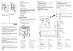
Wiring diagram FT
… Wiring diagram àà àà àà àà àà àà àà Erstinbetriebnahme Aufputzgehäuse Schaltleistung max. 100 mA bei 24 V DC Stromaufnahme LED 2,5 mA bei 24 V Glasscheibe auswechselbar –10 °C ...+55 °C nur für trockene Räume Lieferbare Farbe: àà orange (RAL 2011) XX XX XX XX àà The RWA button FT4 A/24 V DC is used for manual triggering in the event of a hazard (fire). àà The RWA button is a secondary unit with only one display for alarm. àà Can only be used in combination with a main FT4 A button. àà Surface-mounted housing àà Switching power max. 100 mA at 24 V DC àà Current consumption LED … mA at 24 V àà Glass pane replaceable àà –10 °C ...+55 °C àà only for dry rooms àà Colour available: àà orange (RAL 2011) XX Initial operation RWA-Taster nach den Anschlussplänen der verwendeten Notstromsteuerzentrale anschließen. Funktion testen. Beschriftungsschild "RAUCHABZUG" in gewünschter Sprache anbringen (siehe nächste Seite). Nach erfolgreichem Funktionstest Tür des RWA-Tasters öffnen und Karton hinter der Glasscheibe entnehmen. Falls die Taste ZU/Reset nicht angeschlossen ist, Beschriftung „Reset“ (2) abkleben. Anschluss und Innenschaltung XX XX XX XX XX XX Connect the RWA button according to the wiring diagrams for the emergency power control unit used. Test function. Apply the label "SMOKE VENT" in the desired language. After the successful function test, open the door of the RWA button and remove the card cover from behind the glass pane. If the CLOSE/RESET switch is not connected, paste over the "Reset" label (2). Connection and inner circuit XX Die Darstellung zeigt den RWA-Taster mit geöffneter Tür. DIP-Schalter S3 (3) / DIP switch S3 (3): ON Überwachungswiderstände aktiv, im letzten RWA-Taster der Reihe … 126 Sicherheitshinweise / Safety instructions àà Der RWA-Taster darf nur in Verbindung mit GEZE-Notstromsteuerzentralen E 260 N (VdS), MBZ 300, THZ und THZ Comfort eingesetzt werden. àà Der Anschluss erfolgt gemäß dem Anschlussplan der Notstromsteuerzentrale. àà Die Leitungsverlegung und der Anschluss darf nur von einer zugelassenen Elektrofirma vorgenommen werden. XX Bestimmungen der örtlichen Feuerwehr und lokale Anforderungen an RWA-Taster beachten. XX Klebeschild mit Angabe der RWA-Taster-Nummer bauseits auf die Innenseite des RWA-Tasters kleben. XX RWA-Taster vor Bauschmutz schützen. àà The RWA button may only be used in combination with GEZE emergency power control units E 260 N (VdS), MBZ 300, THZ and THZ Comfort. àà Connection is made in accordance with the wiring diagram for the emergency power control unit. àà Laying and connection of cables may only be carried out by an approved electrician. XX Observe any conditions prescribed by the local fire brigade and observe local requirements for RWA buttons. XX Apply the sticker with details of the RWA button number onto the inside of the RWA button on site. XX Protect the RWA button from building dirt. Kurzbeschreibung / Brief description àà Der RWA-Taster FT4 A/24 V DC dient zur manuellen Auslösung bei Gefahr (Feuer). àà Der RWA Taster ist eine Nebenbedienstelle mit nur einer Anzeige für Alarm . àà Nur in Kombination mit einer Hauptbedienstelle FT4 A einsetzbar.
(PDF | 594 KB)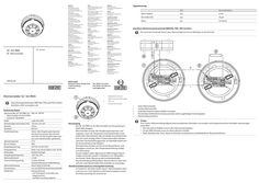
Wiring diagram heat detector GC 163 RWA
… wiring diagram) Smoke detector connection Test Use heat detector testing device from a recognised manufacturer for testing in accordance with the manufacturer’s instructions. àà The red LED on the detector must change to the alarm state. àà An alarm must be activated on the RWA control unit. àà After the test has been completed, reset the alarm on the control unit and carry out a detector line reset.
(PDF | 5 MB)
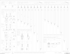
Additional wiring diagram TSA 160 NT TANDEM
… diagram applies in addition to connection diagram DCU5, Mat. No. 125014. Two drives TSA 160 NT are mechanically connected to form a tandem drive. The safety and actuation units must be connected at the DCU5 Master Control unit. The DCU5 control units can be configured with the buttons S1 and S2 or by using the Display program switch. Configuration at the Master- und Slave-control unit: DCU5 Master DCU5 Slave EF = 01 SI = according to desired function SO = 01 TE = depending on the used sensor EF = 02 SI = 00 SO = 01 TE = 00
(PDF | 135 KB)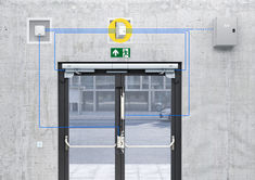
Wiring diagram GC lock SHEV

Block diagram OL 320
(DWG | 1 MB)
Block diagram E 250 NT
(DWG | 1 MB)
Block diagram E 250 NT
(PDF | 435 KB)
Block diagrams ECchain
(DWG | 1 MB)